Setting up environment #
For detailed instructions on NORVI ESP32 HMI,
Installing the Arduino IDE and adding the board, please refer to the Getting Started with NORVI ESP32 HMI document. Getting Started with NORVI ESP32 HMI provides step-by-step guidance on the setup process and Arduino Graphics Library Examples.
Setting up the environment for Arduino LVGL Examples, please refer to the LVGL Example Guide for NORVI ESP32 HMI document. LVGL Example Guide for NORVI ESP32 HMI provides step-by-step guidance on the setup process of LVGL Library examples.
Setting up the environment for NORVI ESP32 HMI with Squareline Studios please refer to the SQUARELINE STUDIOS FOR NORVI ESP32 HMI GUI DESIGN. SQUARELINE STUDIOS FOR NORVI ESP32 HMI GUI DESIGN provides step-by-step guidance on the setup process of designing GUI with Square Line Studios.
For detailed instructions on MODBUS RTU communication through NORVI devices,
The process of NORVI acting as a MODBUS slave and interaction between the NORVI device and MODBUS master simulator, please refer to the NORVI device as a MODBUS RTU SLAVE document. This document examines how to read the digital inputs, and analog input and store the values in the Modbus Software, and the relay/transistor outputs are controlled from the Modbus software.
The process of NORVI acting as a MODBUS master and the interaction between the NORVI device and MODBUS Slave simulator, please refer to the NORVI device as a MODBUS RTU MASTER document. This document examines how to read the values of the digital inputs, analog inputs, and relay/transistor outputs from the MODBUS Software and store the values in the NORVI device.
For the process of MODBUS communication through two NORVI devices, please refer to the MODBUS RTU COMMUNICATION THROUGH NORVI document. This document considers one NORVI device as a slave and the other one as a master and reads the digital inputs, and analog inputs and stores the values in the master device.
Setting up the environment for SquareLine Studio #
Adding supported libraries
Download the LVGL Demo folder for the essential libraries, and files. Copy the libraries from the downloaded LVGL Demo folder into the Arduino/library folder. If there are already downloaded library files, please replace them with these library files.

Initiating a Project with SquareLine Studio
- Create a project
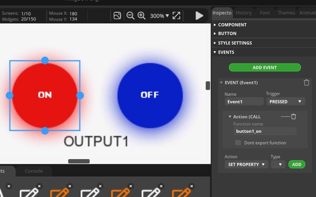
Create a GUI with SquareLine Studio to control LED lights seamlessly. The project has to be configured to activate the LED when the “ON” button is pressed deactivate it when the “OFF” button is pressed and write the coils as MODBUS master.
- Incorporate the buttons from the widgets bar. Utilize the Inspector Bar to configure the button’s style settings, tailoring its appearance to suit your design preferences.

- Furthermore, leverage the Inspector Bar to add events to the button. When defining actions for events in SquareLine Studio, it is important to choose actions that align with the event’s purpose. In the context of LED on and off, “call function” must be selected.

- Incorporate the labels from the widgets bar. Utilize the Inspector Bar to configure the text that should be included in the label and to configure the label’s style settings, tailoring its appearance to suit your design preferences.


- It should incorporate custom fonts when adding labels within SquareLine Studio.
- Download a preferred font and seamlessly integrate it into the project by utilizing the “ADD FILE INTO ASSETS” option located at the bottom of the software interface.
- Craft a font to your project’s needs by navigating to the ‘font menu’ located in the top right corner of SquareLine Studio.
- Select the desired size, allowing for meticulous customization of the font to suit the project’s requirements.

- Then the font can be selected when changing the label settings.

- Make all the buttons, complement the previously configured buttons. Then the entire project comes together seamlessly.
- Select the File/Project Settings and make the changes in the pop-up window. Browse the project export route open a new folder rename it and select. Same as before browse the UI file export path and select the folder that was created earlier.
- After making the changes, proceed by selecting “APPLY CHANGES” located in the lower right corner.

- Then select File/Save to save the project file and Export/Export UI Files to export the project.
2. Pre-requisites.
Copy the ESP32_Display_Squareline_button_Demo folder from the downloaded LVGL Demo/NORVI Squareline demo folder and paste it to the location of the created SQ_MODBUS project folder.

Copy all the files including the insides of the folders in the created SQ_MODBUS project folder and paste them to the ESP32_Display_Squareline_button_Demo folder in the SQ_MODNUS project folder.

Open ui_Screen1.c remove “. . /” and save. If the project contains images and fonts, do the same for those files.

Since this project controls and outputs, the code must have some modifications. Because of the function called when creating the project.
For that, open the ESP32_Display_Squareline_button_Demo.ino file in the SQ_MODBUS project folder. Also, open the MASTER_TRANS_HMI.ino file in the LVGL Demo folder.
Without the inside part of the void loop() add all the parts of the the MASTER_TRANS_HMI.ino file to the ESP32_Display_Squareline_button Demo.ino file to the correct places.
Then select the ui_events.c in ESP32_Display_Squareline_button_Demo.ino file and copy and paste it into the main code, (before the void setup() function). Then do the modifications as shown in the figure.
Comment the full code of the ui_events.c.

Choose the chip and settings according to the chip as shown below.

3. Compile and Upload.
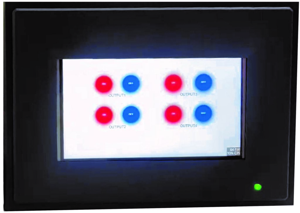
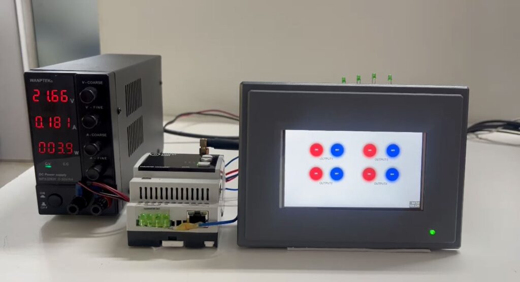
Check the pin configuration of the program. After compiling and uploading the program, the User interface of the NORVI HMI should be as below.

Setting up the environment for MODBUS communication #
- Wiring setup
For the wiring, we need to connect NORVI device RS485 A and B pins with the NORVI ESP32 HMI RS485 terminals.
NROVI ESP32 HMI has a 4-wire RS485 connection. So it has terminals A, B, Y, and Z. Connect Y to A and Z to B. Then, A and B should be connected to the RS485 A and B terminals of the slave device. 24V DC Voltage should be supplied to both devices.
- Slave device setup
The slave program should be uploaded to the slave device. Since the HMI was programmed to write the coils, the slave should be programmed to store the coil values.
Open the SLAVE_TRANS_GSM_O8_T_L.ino file in the SQ_MODBUS project folder. Upload the program to the Slave device. before uploading the program check the SLAVE ID, RS485 RX, TX, and FC pins.
Look at the Serial window of the SLAVE device. The status of the outputs is low because the master is writing low. This means HMI outputs are turned off.

The status of the outputs is high because the master is writing high. This means HMI outputs are turned on.

Understanding the Test program MASTER_TRANS_HMI #
MOSBUS writes coil values program for Norvi HMI.
Add the required library
#include "Wire.h"
#include <ModbusMaster.h>
Definitions for pins such as SDA, SCL, PCA9538 address, and register addresses.
#define SDA 19
#define SCL 20

// I2C address of PCA9538
#define PCA9538_ADDR 0x73

// PCA9538 register addresses
#define PCA9538_INPUT_REG 0x00
#define PCA9538_OUTPUT_REG 0x01
#define PCA9538_POLARITY_REG 0x02
#define PCA9538_CONFIG_REG 0x03
Definitions for FC, RX_PIN, TX_PIN, GPIOs, and the number of output pins.
#define FC    -1
#define RX_PIN 48
#define TX_PIN 2

#define GPIO5 0x10
#define GPIO6 0x20
#define GPIO7 0x40
#define GPIO8 0x80

#define NUM_OUTPUT_PINS 4
Functions to interact with PCA9538 GPIO expander chip.
- setPinMode: Sets the mode (input/output) for a GPIO pin.
- writeOutput: Writes a value (HIGH/LOW) to a GPIO pin.
- readInput: Reads the input value from the GPIO expander.
- readRegister: Reads a register from the PCA9538 chip.
- writeRegister: Writes a value to a register on the PCA9538 chip.
void setPinMode(uint8_t pin, uint8_t mode) {
  uint8_t config = readRegister(PCA9538_CONFIG_REG);
  if (mode == INPUT) {
    config |= pin;
  } else {
    config &= ~pin;
  }
  writeRegister(PCA9538_CONFIG_REG, config);
}

void writeOutput(uint8_t pin, uint8_t value) {
  uint8_t output = readRegister(PCA9538_OUTPUT_REG);
  if (value == LOW) {
    output &= ~pin;
  } else {
    output |= pin;
  }
  writeRegister(PCA9538_OUTPUT_REG, output);
}
uint8_t readInput() {
  return readRegister(PCA9538_INPUT_REG);
}

uint8_t readRegister(uint8_t reg) {
  Wire.beginTransmission(PCA9538_ADDR);
  Wire.write(reg);
  Wire.endTransmission(false);
  Wire.requestFrom(PCA9538_ADDR, 1);
  return Wire.read();
}

void writeRegister(uint8_t reg, uint8_t value) {
  Wire.beginTransmission(PCA9538_ADDR);
  Wire.write(reg);
  Wire.write(value);
  Wire.endTransmission();
}
Variables for storing LED states and a ModbusMaster instance.
ModbusMaster node;
int LED1;
int LED2;
int LED3;
int LED4;
Callback functions for Modbus transmission.
void preTransmission()
{
  digitalWrite(FC, 1);
}

void postTransmission()
{
  digitalWrite(FC, 0);
}
Setup function:
Initializes serial communication. Sets up GPIO pins, I2C communication, and Modbus communication. Begin Modbus communication with a specific slave ID.
void setup()
{
  Serial.begin(9600);
  pinMode(FC, OUTPUT);
  digitalWrite(FC, 0);

  Serial1.begin(9600, SERIAL_8N1, RX_PIN, TX_PIN);

  Wire.begin(SDA, SCL);
  setPinMode(GPIO5, OUTPUT);
  setPinMode(GPIO6, OUTPUT);
  setPinMode(GPIO7, OUTPUT);
  setPinMode(GPIO8, OUTPUT);

  node.begin(5, Serial1);                           //Slave ID as 1
  node.preTransmission(preTransmission);
  node.postTransmission(postTransmission);
}
Loop Function:
- Turns on and off the LEDs and writes its state to the GPIO pins.
- Writes the state of the LED to a specific coil address using Modbus.
void loop()
{
  LED1 = 1;
  writeOutput(GPIO5, LED1);
  writeOutput(GPIO6, 0);
  writeOutput(GPIO7, 0);
  writeOutput(GPIO8, 0);

  uint8_t result;
  result = node.writeSingleCoil(0x00001, LED1);
  delay(5000);
  LED1 = 0;
  writeOutput(GPIO5, LED1);
  writeOutput(GPIO6, 0);
  writeOutput(GPIO7, 0);
  writeOutput(GPIO8, 0);

  result = node.writeSingleCoil(0x00001, LED1);
  delay(2000);

  LED2 = 1;
  writeOutput(GPIO5, 0);
  writeOutput(GPIO6, LED2);
  writeOutput(GPIO7, 0);
  writeOutput(GPIO8, 0);

  result = node.writeSingleCoil(0x00002, LED2);
  delay(5000);
  LED2 = 0;
  writeOutput(GPIO5, 0);
  writeOutput(GPIO6, LED2);
  writeOutput(GPIO7, 0);
  writeOutput(GPIO8, 0);

  result = node.writeSingleCoil(0x00002, LED2);
  delay(2000);

  LED3 = 1;
  writeOutput(GPIO5, 0);
  writeOutput(GPIO6, 0);
  writeOutput(GPIO7, LED3);
  writeOutput(GPIO8, 0);

  result = node.writeSingleCoil(0x00003, LED3);
  delay(5000);
  LED3 = 0;
  writeOutput(GPIO5, 0);
  writeOutput(GPIO6, 0);
  writeOutput(GPIO7, LED3);
  writeOutput(GPIO8, 0);

  result = node.writeSingleCoil(0x00003, LED3);
  delay(2000);

  LED4 = 1;
  writeOutput(GPIO5, 0);
  writeOutput(GPIO6, 0);
  writeOutput(GPIO7, 0);
  writeOutput(GPIO8, LED4);

  result = node.writeSingleCoil(0x00004, LED4);
  delay(5000);
  LED4 = 0;
  writeOutput(GPIO5, 0);
  writeOutput(GPIO6, 0);
  writeOutput(GPIO7, 0);
  writeOutput(GPIO8, LED4);

  result = node.writeSingleCoil(0x00004, LED4);
  delay(2000);
}
Understanding the Test program ESP32 Display Squareline button Demo. #
Add the required library
#include <Wire.h>
#include <SPI.h>
#include <ModbusMaster.h>
#include <lvgl.h>
#include "ui.h"
#include <Arduino_GFX_Library.h>
#include "touch.h"
Definitions for pins such as SDA, SCL, TFT_BL, and GPIOs.
#define SDA 19
#define SCL 20

#define TFT_BL -1
#define GFX_BL DF_GFX_BL
Functions for configuring and interacting with a PCA9538 GPIO expander chip.
#define PCA9538_ADDR 0x73

// PCA9538 register addresses
#define PCA9538_INPUT_REG 0x00
#define PCA9538_OUTPUT_REG 0x01
#define PCA9538_POLARITY_REG 0x02
#define PCA9538_CONFIG_REG 0x03
Definitions for FC, RX_PIN, TX_PIN, and GPIOs.
#define FC    -1
#define RX_PIN 48
#define TX_PIN 2

#define GPIO5 0x10
#define GPIO6 0x20
#define GPIO7 0x40
#define GPIO8 0x80
Variables for storing LED states and a ModbusMaster instance. Pre and Post-Transmission Callback Functions.
ModbusMaster node;
int LED1;
int LED2;
int LED3;
int LED4;

void preTransmission()
{
  digitalWrite(FC, 1);
}

void postTransmission()
{
  digitalWrite(FC, 0);
}
Configuration for driving an RGB display using different libraries (Arduino_ESP32RGBPanel and Arduino_RPi_DPI_RGBPanel).
Arduino_ESP32RGBPanel *bus = new Arduino_ESP32RGBPanel(
    GFX_NOT_DEFINED /* CS */, GFX_NOT_DEFINED /* SCK */, GFX_NOT_DEFINED /* SDA */,
    4 /* DE */, 5 /* VSYNC */, 6 /* HSYNC */, 7 /* PCLK */,
    1 /* R0 */, 41 /* R1 */, 40 /* R2 */, 38 /* R3 */, 45 /* R4 */,
    47 /* G0 */, 21 /* G1 */, 14 /* G2 */, 9 /* G3 */, 3 /* G4 */, 3 /* G5 */,
    8 /* B0 */, 18 /* B1 */, 17 /* B2 */, 16 /* B3 */, 15 /* B4 */
);
Arduino_RPi_DPI_RGBPanel *lcd = new Arduino_RPi_DPI_RGBPanel(
    bus,
    800 /* width */, 0 /* hsync_polarity */, 210 /* hsync_front_porch */, 30 /* hsync_pulse_width */, 16 /* hsync_back_porch */,
    480 /* height */, 0 /* vsync_polarity */, 22 /* vsync_front_porch */, 13 /* vsync_pulse_width */, 10 /* vsync_back_porch */,
    1 /* pclk_active_neg */, 16000000 /* prefer_speed */, true /* auto_flush */);
Touch Panel Configuration:
#include "touch.h"

#ifdef USE_UI
/* Change to your screen resolution */
static uint32_t screenWidth;
static uint32_t screenHeight;
static lv_disp_draw_buf_t draw_buf;
static lv_color_t disp_draw_buf[800 * 480 / 10];      //5,7inch: lv_color_t disp_draw_buf[800*480/10]            4.3inch: lv_color_t disp_draw_buf[480*272/10]
//static lv_color_t disp_draw_buf;
static lv_disp_drv_t disp_drv;

/* Display flushing */
void my_disp_flush(lv_disp_drv_t *disp, const lv_area_t *area, lv_color_t *color_p)
{
  uint32_t w = (area->x2 - area->x1 + 1);
  uint32_t h = (area->y2 - area->y1 + 1);

#if (LV_COLOR_16_SWAP != 0)
  lcd->draw16bitBeRGBBitmap(area->x1, area->y1, (uint16_t *)&color_p->full, w, h);
#else
  lcd->draw16bitRGBBitmap(area->x1, area->y1, (uint16_t *)&color_p->full, w, h);
#endif

  lv_disp_flush_ready(disp);
}

void my_touchpad_read(lv_indev_drv_t *indev_driver, lv_indev_data_t *data)
{
  if (touch_has_signal())
  {
    if (touch_touched())
    {
      data->state = LV_INDEV_STATE_PR;

      /*Set the coordinates*/
      data->point.x = touch_last_x;
      data->point.y = touch_last_y;
      Serial.print( "Data x :" );
      Serial.println( touch_last_x );

      Serial.print( "Data y :" );
      Serial.println( touch_last_y );
    }
    else if (touch_released())
    {
      data->state = LV_INDEV_STATE_REL;
    }
  }
  else
  {
    data->state = LV_INDEV_STATE_REL;
  }
  // delay(15);
}
#endif
Functions for handling button events such as turning LEDs on and off.
uint8_t result;
void button1_on(lv_event_t * e)
{
  LED1 = 1;
	writeOutput(GPIO5, 0);
  result = node.writeSingleCoil(0x00001, LED1);
}
void button1_off(lv_event_t * e)
{
  LED1 = 0;
	writeOutput(GPIO5, 1);
  result = node.writeSingleCoil(0x00001, LED1);
}
void button2_on(lv_event_t * e)
{
  LED2 = 1;
  writeOutput(GPIO6, 0);
  result = node.writeSingleCoil(0x00002, LED2);
}
void button2_off(lv_event_t * e)
{
  LED2 = 0;
  writeOutput(GPIO6, 1);
  result = node.writeSingleCoil(0x00002, LED2);
}
void button3_on(lv_event_t * e)
{
  LED3 = 1;
  writeOutput(GPIO7, 0);
  result = node.writeSingleCoil(0x00003, LED3);
}
void button3_off(lv_event_t * e)
{
  LED3 = 0;
  writeOutput(GPIO7, 1);
  result = node.writeSingleCoil(0x00003, LED3);
}
void button4_on(lv_event_t * e)
{
  LED4 = 1;
  writeOutput(GPIO8, 0);
  result = node.writeSingleCoil(0x00004, LED4);
}
void button4_off(lv_event_t * e)
{
  LED4 = 0;
  writeOutput(GPIO8, 1);
  result = node.writeSingleCoil(0x00004, LED4);
}
Setup Function:
Initialization code includes serial communication, Modbus setup, display setup, LVGL initialization, and GPIO setup.
void setup()
{
  Serial.begin(9600);
  Serial.println("LVGL Widgets Demo");

  pinMode(FC, OUTPUT);
  digitalWrite(FC, 0);

  Serial1.begin(9600, SERIAL_8N1, RX_PIN, TX_PIN);
  node.begin(5, Serial1);                           //Slave ID as 5
  node.preTransmission(preTransmission);
  node.postTransmission(postTransmission);

// #if defined(Display_50) || defined(Display_70)
//IO Port Pins
   pinMode(38, OUTPUT);
   digitalWrite(38, LOW);
   pinMode(17, OUTPUT);
   digitalWrite(17, LOW);
   pinMode(18, OUTPUT);
   digitalWrite(18, LOW);
/   pinMode(42, OUTPUT);
   digitalWrite(42, LOW);
  #elif defined(Display_43)
   pinMode(20, OUTPUT);
   digitalWrite(20, LOW);
   pinMode(19, OUTPUT);
   digitalWrite(19, LOW);
   pinMode(35, OUTPUT);
   digitalWrite(35, LOW);
   pinMode(38, OUTPUT);
   digitalWrite(38, LOW);
   pinMode(0, OUTPUT);//TOUCH-CS
 #endif

  // Init Display
  lcd->begin();
  lcd->fillScreen(BLACK);
  lcd->setTextSize(2);
  // delay(20);

#ifdef USE_UI
  lv_init();

  // delay(100);
  touch_init();

  screenWidth = lcd->width();
  screenHeight = lcd->height();

  lv_disp_draw_buf_init(&draw_buf, disp_draw_buf, NULL, screenWidth * screenHeight / 10);
  //  lv_disp_draw_buf_init(&draw_buf, disp_draw_buf, NULL, 480 * 272 / 10);
  /* Initialize the display */
  lv_disp_drv_init(&disp_drv);
  /* Change the following line to your display resolution */
  disp_drv.hor_res = screenWidth;
  disp_drv.ver_res = screenHeight;
  disp_drv.flush_cb = my_disp_flush;
  disp_drv.draw_buf = &draw_buf;
  lv_disp_drv_register(&disp_drv);

  /* Initialize the (dummy) input device driver */
  static lv_indev_drv_t indev_drv;
  lv_indev_drv_init(&indev_drv);
  indev_drv.type = LV_INDEV_TYPE_POINTER;
  indev_drv.read_cb = my_touchpad_read;
  lv_indev_drv_register(&indev_drv);
#endif

#ifdef TFT_BL
  pinMode(TFT_BL, OUTPUT);
  digitalWrite(TFT_BL, HIGH);
#endif

#ifdef USE_UI
  ui_init();//ui from Squareline or GUI Guider
#else
  lcd->fillScreen(RED);
  // delay(80);
  lcd->fillScreen(BLUE);
  // delay(80);
  lcd->fillScreen(YELLOW);
  // delay(80);
  lcd->fillScreen(GREEN);
  // delay(80);
#endif
  Serial.println( "Setup done" );

  Wire.begin(SDA, SCL);
  setPinMode(GPIO5, OUTPUT);
  setPinMode(GPIO6, OUTPUT);
  setPinMode(GPIO7, OUTPUT);
  setPinMode(GPIO8, OUTPUT);
}
Loop Function:
Contains a while(1) loop which is expected to handle LVGL timer events.
void loop()
{
  while(1)
  {
#ifdef USE_UI
    lv_timer_handler();
    // delay(5);
#endif
  }
}


