Programming #
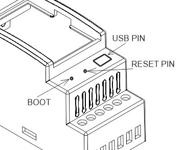
The NORVI AGENT 1-BT01-ES-N has a mini USB port for serial connection with the SoC for programming. Any ESP32-supported programming IDE can be used to program the controller. Follow this Guide to programming NORVI ESP32-based controllers with the Arduino IDE.
SoC: ESP32-WROVER-B
Programming Port: USB UART
Digital Inputs #
Wiring Digital Inputs #
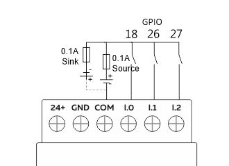
The digital inputs of NORVI AGENT 1-BT01-ES-N can be configured as both sink and source connections. The inverse of the Digital Input polarity should be supplied to the common terminal.
Programming Digital Inputs #
Reading the relevant GPIO of the ESP32 gives the value of the Digital Input. When the inputs are in the OFF state, the GPIO goes HIGH, and when the input is in the ON state, the GPIO goes LOW. Refer to the GPIO allocation table in the datasheet for the digital input GPIO.
#define INPUT1 18
void setup() {
   Serial.begin(115200);
   Serial.println("Device Starting");

   pinMode(INPUT1, INPUT);
}
void loop() {
   Serial.print(digitalRead(INPUT1));
   Serial.println("");
   delay(500);
}
0 – 10V Analog Input #
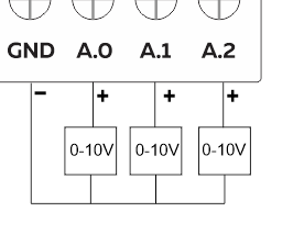
Wiring Analog Inputs #
Reading Analog Input #
Reading the relevant I2C address of the ADC gives the value of the Analog Input.

Programming Analog Inputs #
#include <Adafruit_ADS1X15.h>
#include <Wire.h>
Adafruit_ADS1115 ads1;

void setup() {
  Serial.begin(115200);
  Serial.println("Device Starting");
  Wire.begin(21,22);
  ads1.begin(0x48);
  ads1.setGain(GAIN_ONE);
}

void loop() {
  Serial.print("Analog 0 ");
  Serial.println(ads1.readADC_SingleEnded(0));
  delay(10);
  Serial.print("Analog 1 ");
  Serial.println(ads1.readADC_SingleEnded(1));
  delay(10);
  Serial.print("Analog 2 ");
  Serial.println(ads1.readADC_SingleEnded(2));
  delay(10);
  Serial.println("");
  delay(500);
}
Transistor Output #
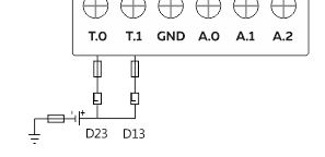
Wiring Transistor Outputs #
Programming Transistor Outputs #
Reading the relevant GPIO of the ESP32 gives the value of the Transistor Output. Refer to the GPIO allocation table in the datasheet for the Transistor Output GPIO.
#define OUTPUT1 23
void setup() {
   Serial.begin(115200);
   Serial.println("Device Starting");
   pinMode(OUTPUT1 , OUTPUT);
}
void loop() {
   digitalWrite(OUTPUT1, HIGH);
   delay(500);
   digitalWrite(OUTPUT1, LOW);
   delay(500);
   Sirial.println("");
   delay(500);
}
Built-in Buttons #
| Button 1 Pin | Digital Input GPIO35 |
Programming Buttons #
#include <Adafruit_NeoPixel.h>
#define BUTTON_PIN   35    //Digital IO pin connected to the button. This will be
#define PIXEL_PIN    25    // Digital IO pin connected to the NeoPixels.
#define PIXEL_COUNT 1

Adafruit_NeoPixel strip = Adafruit_NeoPixel(PIXEL_COUNT, PIXEL_PIN, NEO_GRB + NEO_KHZ800);
bool oldState = HIGH;
int showType = 0;

void setup() {
  Serial.begin(115200);
  pinMode(BUTTON_PIN, INPUT_PULLUP);
  strip.begin();
  strip.show(); // Initialize all pixels to 'off'
  Serial.println("RS-485 TEST");
}

void loop() {
  bool newState = digitalRead(BUTTON_PIN);
  if (newState == LOW && oldState == HIGH) {
    delay(20);
    newState = digitalRead(BUTTON_PIN);
    if (newState == LOW) {
      showType++;
      if (showType > 9)
        showType = 0;
      startShow(showType);
    }
  }
  oldState = newState;
}

void startShow(int i) {
  switch (i) {
    case 0: colorWipe(strip.Color(0, 0, 0), 50);   break;
    case 1: colorWipe(strip.Color(255, 0, 0), 50); break;
    case 2: colorWipe(strip.Color(0, 255, 0), 50); break;
    case 3: colorWipe(strip.Color(0, 0, 255), 50); break;
    case 4: theaterChase(strip.Color(127, 127, 127), 50); break;
    case 5: theaterChase(strip.Color(127, 0, 0), 50); break;
    case 6: theaterChase(strip.Color(0, 0, 127), 50); break;
    case 7: rainbow(20); break;
    case 8: rainbowCycle(20); break;
    case 9: theaterChaseRainbow(50); break;
  }
}
NB-IoT Module #
| Modem | NB-101 |
| RX | GPIO4 |
| TX | GPIO2 |
| RESET | GPIO19 |
Programming NB-IoT #
#define RXD2 4
#define TXD2 2
#define PIN  5
#define RES  19

void setup() {
  // initialize both serial ports:
  Serial.begin(9600);
  Serial2.begin(9600, SERIAL_8N1, RXD2, TXD2);
  pinMode(PIN,OUTPUT);
  pinMode(RES,OUTPUT);
  digitalWrite(RES,HIGH);
  digitalWrite(PIN,HIGH);
}

void loop() {
  //Serial2.println("AT");
  //delay(300);
  // read from port 1, send to port 0:
  if (Serial2.available()) {
    int inByte = Serial2.read();
    Serial.write(inByte);
  }
  // read from port 0, send to port 1:
  if (Serial.available()) {
    int inByte = Serial.read();
    Serial2.write(inByte);
  }
}
USB and Reset #