Programming #
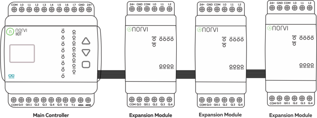
NORVI-EX-I16 uses MCP23017 over I2C communication. The I2C addresses of the devices can be configured with the DIP switches at the bottom of the controller. It can Daisy chain up to eight expansion modules.
Expansion Port #
The expansion port of the NORVI IIOT Controllers can be utilized for external sensor connections where raw GPIO connections are required, or they can be used to plug NORVI Expansion Modules. Browse the NORVI Expansion Product Range. How to Connect NORVI Expansion Modules


I2C Address Setting #
The I2C address of the expansion module can be configured by switching DIP switches at the bottom of the expansion module. The device can be configured at 8 I2C addresses using the first 3 DIP switches.

Digital Inputs #
Wiring Digital Inputs #
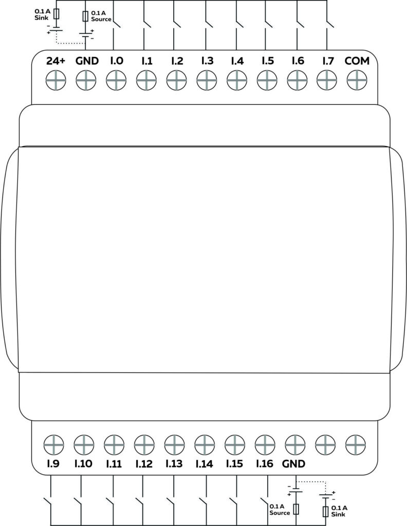
The digital inputs of the NORVI Expansions range can be configured as both a sink and a source connection. The inverse of the digital input polar should be supplied to the common terminal.

Programming Digital Inputs #
Reading the relevant GPIO of MCP230008 gives the value of the digital input. When the inputs are in the OFF state, the GPIO goes HIGH, and when the inputs are in the ON state, the GPIO goes LOW.
Refer to the GPIO Allocation Table for Digital Input GPIO
Refer to the I2C Address setting to set the I2C address of the Expansion
// Blinks an LED attached to a MCP23XXX pin.
// ok to include only the one needed
// both included here to make things simple for example
//#include <Adafruit_MCP23X08.h>
#include <Adafruit_MCP23X17.h>

#define INPUT1 0
#define INPUT2 1
#define INPUT3 2
#define INPUT4 3

#define INPUT5 4
#define INPUT6 5
#define INPUT7 6
#define INPUT8 7

#define INPUT9 8
#define INPUT10 9
#define INPUT11 10
#define INPUT12 11

#define INPUT13 12
#define INPUT14 13
#define INPUT15 14
#define INPUT16 15

// uncomment appropriate line
//Adafruit_MCP23X08 mcp;
Adafruit_MCP23X17 mcp;

void setup() {
  Serial.begin(115200);
  //while (!Serial);
  Serial.println("NORVO Expansions Test");
  // uncomment appropriate mcp.begin
  Wire.begin (16, 17);
  if (!mcp.begin_I2C(0x27)) {
    Serial.println("Error.");
    while (1);
  }
  // configure pin for output
  mcp.pinMode(INPUT1, INPUT);
  mcp.pinMode(INPUT2, INPUT);
  mcp.pinMode(INPUT3, INPUT);
  mcp.pinMode(INPUT4, INPUT);
  mcp.pinMode(INPUT5, INPUT);
  mcp.pinMode(INPUT6, INPUT);
  mcp.pinMode(INPUT7, INPUT);
  mcp.pinMode(INPUT8, INPUT);
  mcp.pinMode(INPUT9, INPUT);
  mcp.pinMode(INPUT10, INPUT);
  mcp.pinMode(INPUT11, INPUT);
  mcp.pinMode(INPUT12, INPUT);
  mcp.pinMode(INPUT13, INPUT);
  mcp.pinMode(INPUT14, INPUT);
  mcp.pinMode(INPUT15, INPUT);
  mcp.pinMode(INPUT16, INPUT);
  Serial.println("Looping...");
}

void loop() {
  Serial.print(mcp.digitalRead(INPUT1));
  Serial.print(mcp.digitalRead(INPUT2));
  Serial.print(mcp.digitalRead(INPUT3));
  Serial.println(mcp.digitalRead(INPUT4));
  Serial.print(mcp.digitalRead(INPUT5));
  Serial.print(mcp.digitalRead(INPUT6));
  Serial.print(mcp.digitalRead(INPUT7));
  Serial.println(mcp.digitalRead(INPUT8));
  Serial.print(mcp.digitalRead(INPUT9));
  Serial.print(mcp.digitalRead(INPUT10));
  Serial.print(mcp.digitalRead(INPUT11));
  Serial.println(mcp.digitalRead(INPUT12));
  Serial.print(mcp.digitalRead(INPUT13));
  Serial.print(mcp.digitalRead(INPUT14));
  Serial.print(mcp.digitalRead(INPUT15));
  Serial.println(mcp.digitalRead(INPUT16));
  Serial.println("Looping...");
  delay(1000);
}


