Product Features #
- Input voltage range up to 10V
- Over-voltage protection
- Programmable Gain Amplifier
Expansions Supported
- Analog Input
- Analog Output
Main #
| Range of Product | NORVI Expansion |
| Product Type | Expansion Module |
| Certifications | EN 61131-2:2007 EN 61010-1:2010+A1:2019 EN IEC 61010-2-201:2018 2014/30/EU- Electromagnetic Compatibility (EMC) Annex III, Part B, Module C |
| Rated supply voltage | 24V DC |
| Communication | WiFI / Bluetooth |
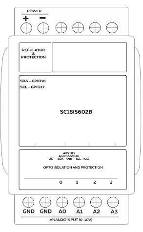
| Inputs and Outputs | 4 x Analog Inputs with 0-10 V |
| Displays and Visual Indicators | 1 LED green |
Complementary #
| Product Unified Code | NORVI EX-ANV01 |
| Product Part Numbers | NORVI EX-ANV01 |
Mechanical Properties #
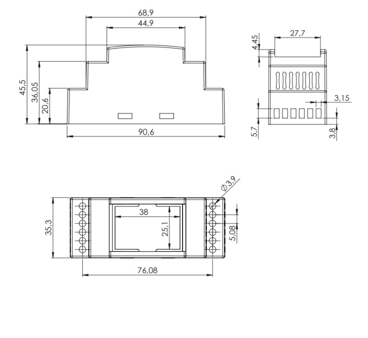
| Enclosure | NORVI 202 |
| Mounting / Installation Method | DIN RAIL / MOUNTING TABS |
| Terminal Type | SCREW TERMINAL |
| Terminal Arrangement | Top and Bottom |
| Length | 59.00 mm |
| Height | 86.00 mm |
| Width | 35.00 mm |
Environment #
| IP degree of protection | IP20 |
| Operating altitude | 0 – 2000 meters |
| Operating Temperature | – –10 … +85° C (14…185 °F) |
| Storage altitude | 0 – 3000 meters |
| Shock resistance | 15 gn for 11ms |
| Resistance to electrostatic discharge | 4kV on contact 8kV on air |
| Resistance to electromagnetic fields | 10 V/m (80 MHz …… 1GHz) 3 V/m (1.4 MHz …… 2 GHz) 1 V/m (2 MHz …… 3 GHz) |
Electrical Characteristics #
Grid Powered Devices #
| Rated Supply Voltage (V) | 24V DC |
| Current Consumption (mA) | 400mA |
| Recommended Power Source | 1A, 24V DC |
Processing #
| SOC / MCU | I2C to SPI connector |
| Module | SC18IS602B |
| Operating supply voltage | 2.4V to 3.6V |
| Resolution | 16bit |
| I2C SDA | GPIO16 |
| I2C SCL | GPIO17 |
INPUTS and OUTPUTS #
Analog Inputs #
| Number of Analog Inputs | 4 |
| Analog Input Measurement Range | 0-10 V |
| Analog Input Maximum Voltage | 38V DC |
| Analog to Digital Converter (ADC) | ADS1115 |
| Analog to Digital Converter (ADC) Communication | I2C |
| Analog to Digital Converter (ADC) Address | 0x48 |
| Terminal Arrangement | A0 : Analog Input 0 – ADS1115 – 0x48 – AIN0 A1 : Analog Input 1 – ADS1115 – 0x48 – AIN1 A2 : Analog Input 2 – ADS1115 – 0x48 – AIN2 A3 : Analog Input 3 – ADS1115 – 0x48 – AIN3 |
Expansion Port #
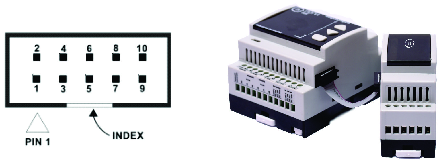
| PIN | ESP32 Connection |
| 1 | TXD0 |
| 2 | GPIO25 |
| 3 | RXD0 |
| 4 | AUX1 |
| 5 | GPIO15 |
| 6 | NRST |
| 7 | SCL2 |
| 8 | AUX2 |
| 9 | SDA2 |
| 10 | GND |


