Product Features #
- ESP32-WROOM32 Module
- NB-IoT module
- Load Cell Input
Main #
| Range of Product | NORVI EC M11 |
| Product Type | Programmable Node |
| Certifications | EN 61131-2:2007 EN 61010-1:2010+A1:2019 EN IEC 61010-2-201:2018 2014/30/EU- Electromagnetic Compatibility (EMC) Annex III, Part B, Module C |
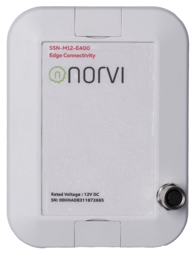
| Rated supply voltage | 24V DC |
| Communication | WiFI / Bluetooth RS 485 |
| Inputs and Outputs | 1 x Load Cell Input |
| Displays and Visual Indicators | Green and Red LED |
Complementary #
| Product Unified Code | NORVI EC-M11-EG-C3-B95 |
| Product Part Numbers | NORVI EC-M11-EG-C3-B95 |
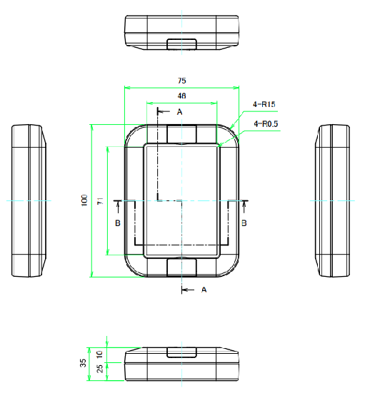
Mechanical Properties #
| Enclosure | WP8-10-4G |
| Mounting / Installation Method | Wall mount Electrical Pole mount – accessory required |
| Terminal Type | 8 Position Molding Cable / AWG24 / Length 2 meters |
| Terminal Arrangement | Color-Coded Tinned Wires |
| Depth | 35 mm |
| Height | 100 mm |
| Width | 75 mm |
Environment #
| IP degree of protection | IP20 |
| Operating altitude | 0 – 2000 meters |
| Operating Temperature | – –10 … +85° C |
| Storage altitude | 0 – 3000 meters |
| Shock resistance | 15 gn for 11ms |
| Resistance to electrostatic discharge | 4kV on contact 8kV on air |
| Resistance to electromagnetic fields | 10 V/m (80 MHz …… 1GHz) 3 V/m (1.4 MHz …… 2 GHz) 1 V/m (2 MHz …… 3 GHz) |
Electrical Characteristics
#
Grid Powered Devices #
| Rated Supply Voltage (V) | 24V DC |
| Current Consumption (mA) | 400mA |
| Recommended Power Source | 1W 24V DC |
Processing #
| SOC / MCU | ESP32-WROOM32 |
| Flash Memory | 4MB |
| ROM | 448 KB |
| SRAM | 520 KB |
| PSRAM | NOT AVAILABLE |
INPUTS and OUTPUTS #
Load Cell Input #
| Number of Load Cell Inputs | 1 |
| Module Type | HX711 |
| PD SCK | GPIO32 |
| DOUT | GPIO33 |
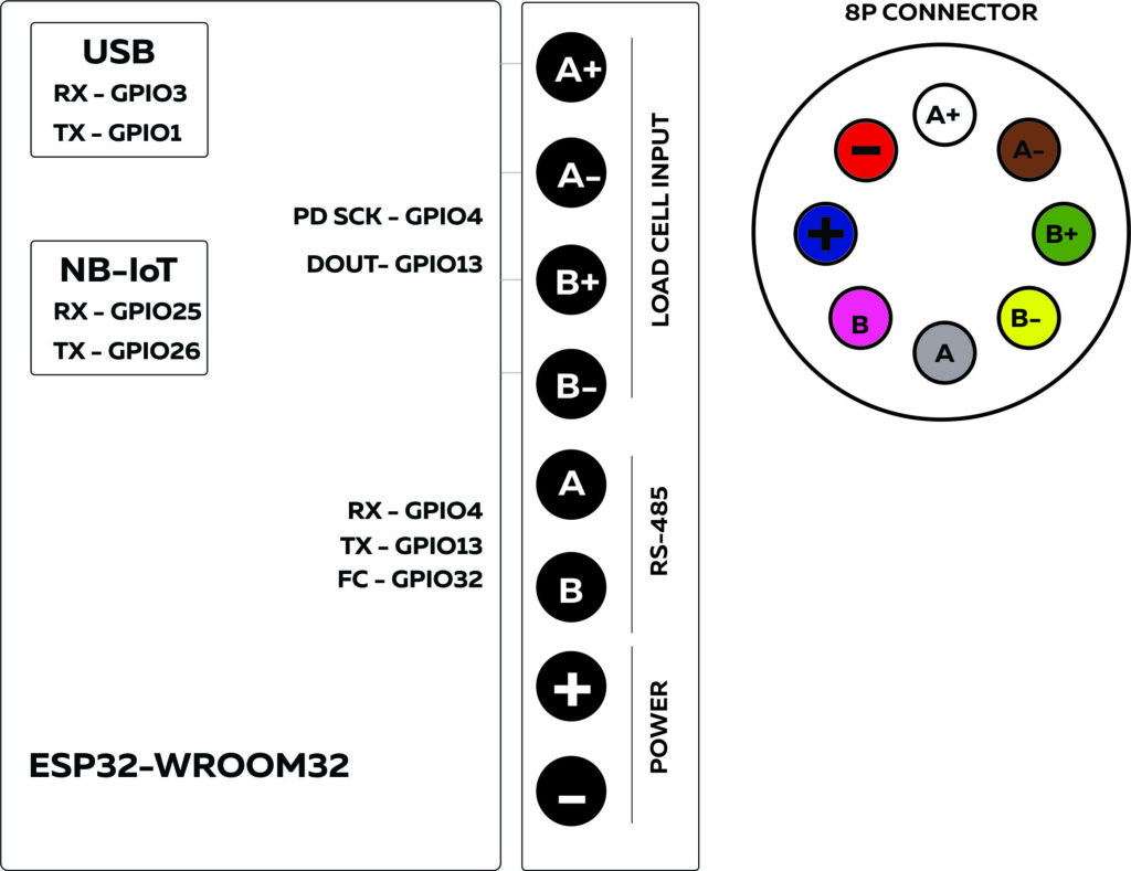
8 Pin Connector and wire harness #
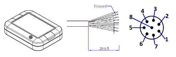
Pin Description #
| 8P Male | Wire colour | I/O Configuration |
| 1 | White | A+ |
| 2 | Brown | A- |
| 3 | Green | B+ |
| 4 | Yellow | B- |
| 5 | Gray | RS-485A |
| 6 | Pink | RS-485B |
| 7 | Blue | Power+ |
| 8 | Red | Power- |
Communication Channels #
RS-485 Communication #
| Communication Mode | HALF-DUPLEX |
| Transceiver | MAX485 |
| Unit Load | 1/4 |
| Flow Control / Direction Control Pin | GPIO13 |
| TX Pin | GPIO2 |
| RX Pin | GPIO4 |
NB-IoT Module #
| Modem | NB-101 |
|---|---|
| RX | GPIO25 |
| TX | GPIO26 |
| POWER | GPIO22 |
| RESET | GPIO17 |
GPIO Map #
| GPIO | Description | Usage |
| 0 | outputs PWM signal at boot | NRST |
| 1 | USB to UART | TX0 |
| 2 | RS-485 | TX1 |
| 3 | USB to UART | RX0 |
| 4 | RS-485 | RX3 |
| 5 | outputs PWM signal at boot | |
| 12 | boot fails if pulled high | |
| 13 | RS-485 | Flow Control |
| 14 | outputs PWM signal at boot | |
| 15 | outputs PWM signal at boot | |
| 16 | ||
| 17 | NB-IoT | RESET |
| 22 | NB-IoT | POWER |
| 23 | ||
| 25 | NB-IoT | RX |
| 26 | NB-IoT | TX |
| 32 | Load Cell Input | PD SCK |
| 33 | Load Cell Input | DOUT |
| 35 | ||
| 36 |


