Product Features #
- RS-485 Communication
- Built-in Button on the front panel
- Digital Inputs
- Relay outputs
- Transistor outputs
- DIN-Rail mount
Expansions Supported
- Digital Input
- Transistor Output
- Relay Output
Main #
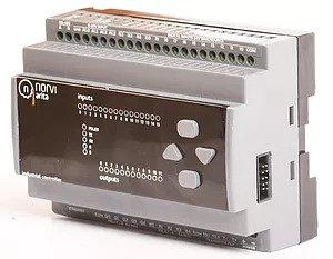
| Range of Product | NORVI ARITA |
| Product Type | Programmable Controller |
| Certifications | EN 61131-2:2007 EN 61010-1:2010+A1:2019 EN IEC 61010-2-201:2018 2014/30/EU- Electromagnetic Compatibility (EMC) Annex III, Part B, Module C |
| Rated supply voltage | 24V DC |
| Communication | I2CRS-485 |
| Inputs and Outputs | 14 x Digital Inputs 10 x Relay Outputs 2 x Transistor Outputs |
| Displays and Visual Indicators | 1 LED green for PWR 1 LED green for RUN 14 LED green for I0……I14 10 LED green for Q0……Q4 and R0…..R4 2 LED green for T0….T1 |
Complementary #
| Product Unified Code | NORVI ARITA-STM32-M6 |
| Product Part Numbers | NORVI ARITA-STM32-M6 |
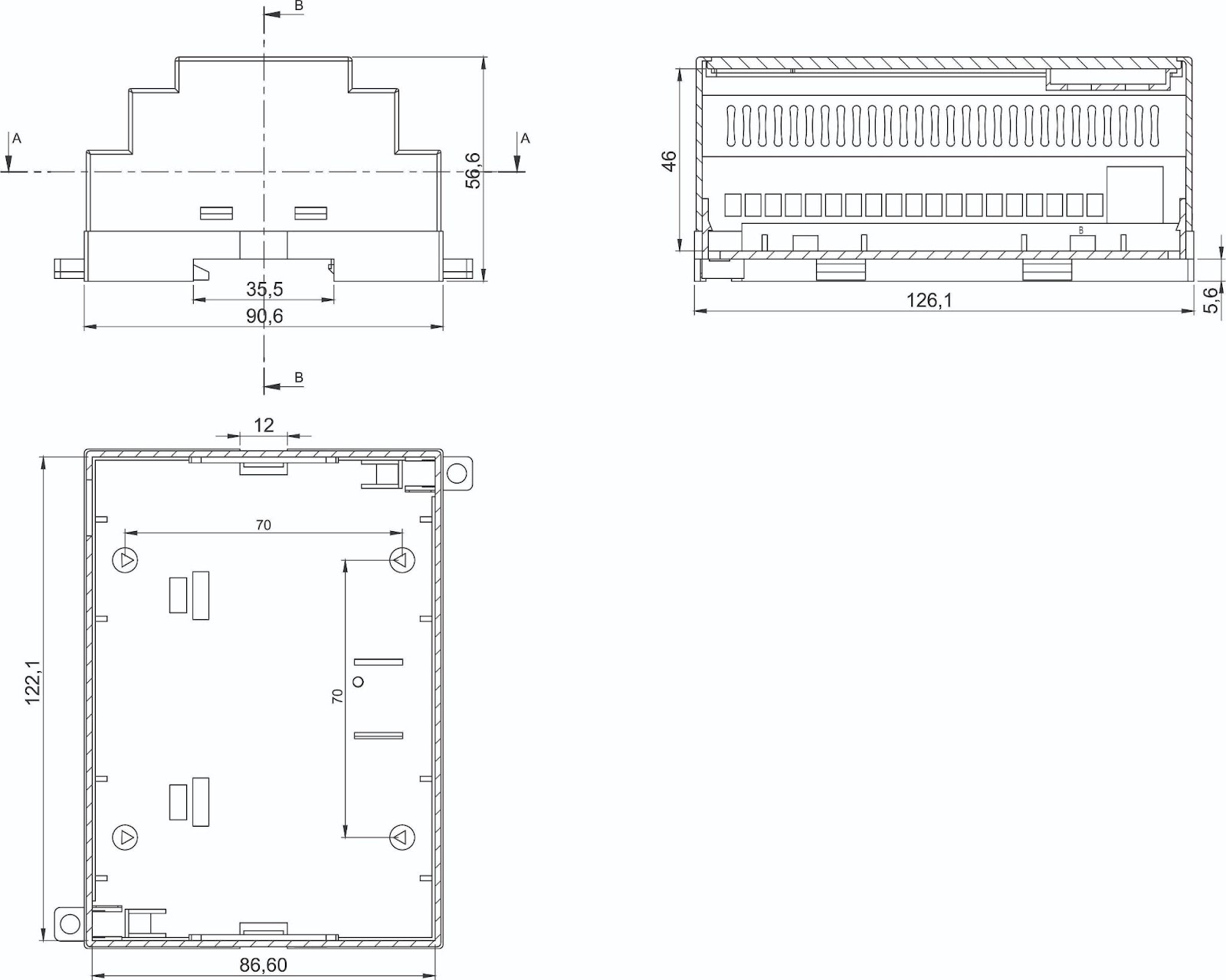
Mechanical Properties #
| Enclosure | NORVI 207 |
| Mounting / Installation Method | DIN RAIL / MOUNTING TABS |
| Terminal Type | Top hat type TH35-15 rail conforming to IEC 60715 Top hat type TH35-7.5 rail conforming to IEC 60715 Plate or panel with fixing kit |
| Terminal Arrangement | Top and Bottom |
| Depth | 56.60 mm |
| Height | 86.60 mm |
| Width | 122.10 mm |
Environment #
| IP degree of protection | IP20 |
| Operating altitude | 0 – 2000 meters |
| Operating Temperature | – –10 … +85° C (14…185 °F) |
| Storage altitude | 0 – 3000 meters |
| Shock resistance | 15 gn for 11ms |
| Resistance to electrostatic discharge | 4kV on contact 8kV on air |
| Resistance to electromagnetic fields | 10 V/m (80 MHz …… 1GHz) 3 V/m (1.4 MHz …… 2 GHz) 1 V/m (2 MHz …… 3 GHz) |
Electrical Characteristics #
Grid Powered Devices #
| Rated Supply Voltage (V) | 24V DC |
| Current Consumption (mA) | 400mA |
| Recommended Power Source | 1A 24V DC |
Processing #
| SOC / MCU | STM32F103RBT6 |
| Flash Memory | 256 to 512 KB |
| SRAM | up to 64 KB |
Peripherals #
Internal RTC #
| RTC Chip | DS1307ZN+ |
| Backup Battery Type | CR2450N-IB |
| Interface | I2C |
| I2C Address | 0x68 |
| SCL Pin | PB6 |
| SDA Pin | PB7 |
Built-in Buttons #
| Button 1 Pin | PC1 |
| Button 2 Pin | PC0 |
| Button 3 Pin | PE6 |
| Button 4 Pin | PE5 |
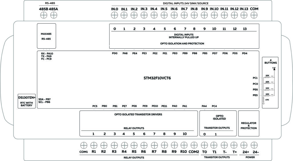
INPUTS and OUTPUTS #
Digital Inputs #
| Number of Digital Inputs | 14 |
| Digital Input Polarity | Sink and Source |
| Digital Input Maximum Voltage | 32V DC |
| Digital Input Minimum Voltage | 18V DC |
| Maximum Switching Frequency | 1 kHZ |
| Terminal Arrangement | Digital Input 1 – PD0 Digital Input 2 – PA8 Digital Input 3 – PE4 Digital Input 4 – PE3 Digital Input 5 – PE2 Digital Input 6 – PE1 Digital Input 7 – PE0 Digital Input 8 – PB9 Digital Input 9 – PB8 Digital Input 10 – PB5 Digital Input 11 – PD7 Digital Input 12 – PD6 Digital Input 13 – PD5 Digital Input 14 – PD4 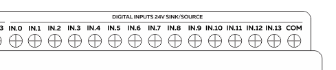 |
Analog Inputs #
| Number of Analog Inputs | 4 |
| Analog Input Measurement Range | 4 – 20mA0 – 10V |
| Analog Input Maximum Voltage | 38V DC |
| Analog to Digital Converter (ADC) | ADS1115 |
| Analog to Digital Converter (ADC) Communication | I2C |
| Analog to Digital Converter (ADC) Address | 0x48 |
| Terminal Arrangement | A0 : Analog Input 0 – ADS1115 – 0x48 – AIN0 – 0 – 10V A1 : Analog Input 1 – ADS1115 – 0x48 – AIN1 – 0 – 10V A2 : Analog Input 2 – ADS1115 – 0x48 – AIN2 – 4 – 20mA A3 : Analog Input 3 – ADS1115 – 0x48 – AIN3 – 4 – 20mA 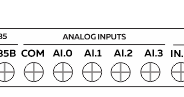 |
Transistor Outputs #
| Number of Transistor Outputs | 2 |
| Transistor Output Type | OPEN COLLECTOR |
| Maximum Sink/Source Current (mA) | 100mA |
| Maximum Applicable Voltage | 40V DC |
| Maximum Switching Frequency | 1 kHz |
| Terminal Arrangement | T0 – PA4 T1 – PC4 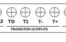 |
Relay Outputs #
| Number of Relay Outputs | 10 |
| Relay Output Type | Normally Open / SPST / Electro-mechanical |
| Contact Current Rating (Resistive) | 5 A 30V DC/250V AC |
| Maximum Contact Voltage | 270V AC, 125V DC |
| Maximum Switching Frequency | 60 Hz |
| Terminal Arrangement | Relay Output 0 – PC5 Relay Output 1 – PB0 Relay Output 2 – PB1 Relay Output 3 – PE7 Relay Output 4 – PE8 Relay Output 5 – PE9 Relay Output 6 – PE10 Relay Output 7 – PE11 Relay Output 8 – PA0 Relay Output 9 – PA1 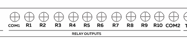 |
Communication Channels #
RS-485 Communication #
| Communication Mode | HALF-DUPLEX |
| Transceiver | MAX485CSA |
| Unit Load | 1/4 |
| Flow Control / Direction Control Pin | PC9 |
| TX Pin | PA9 |
| RX Pin | PA10 |
| Terminal Arrangement | 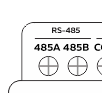 |
Wifi Communication #
| Protocol | Integrated TCP/IP |
| Model Name | ESP8266MOD |
| Operating Voltage | 3.6V |
| Flash | 4M |
| Power Consumption | < 1.0mW |
Bluetooth Communication #
| Model Name | WT51822-S4AT |
| Operating Voltage | 3.3V |
| Flash | 256KB |
| RAM | 16KB |
GPIO Map #
| Pin | GPIO | Usage |
| 1 | PE2 | Digital Input 5 |
| 2 | PE3 | Digital Input 4 |
| 3 | PE4 | Digital Input 3 |
| 4 | PE5 | Button 4 |
| 5 | PE6 | Button 3 |
| 15 | PC0 | Button 2 |
| 16 | PC1 | Button 1 |
| 23 | PA0 | Relay Output 8 |
| 24 | PA1 | Relay Output 9 |
| 25 | PA2 | Expansion RX3 |
| 26 | PA3 | Expansion TX3 |
| 29 | PA4 | Transistor Output 0 |
| 30 | PA5 | Expansion SCK |
| 31 | PA6 | Expansion MISO |
| 32 | PA7 | Expansion MOSI |
| 33 | PC4 | Transistor Output 1 |
| 34 | PC5 | Relay Output 0 |
| 35 | PB0 | Relay Output 1 |
| 36 | PB1 | Relay Output 2 |
| 38 | PE7 | Relay Output 3 |
| 39 | PE8 | Relay Output 4 |
| 40 | PE9 | Relay Output 5 |
| 41 | PE10 | Relay Output 6 |
| 42 | PE11 | Relay Output 7 |
| 47 | PB10 | Expansion SCL |
| 48 | PB11 | Expansion SDA |
| 52 | PB13 | SCK |
| 53 | PB14 | MISO |
| 54 | PB15 | MOSI |
| 64 | PC7 | Bluetooth – Enable |
| 65 | PC8 | Bluetooth – Reset |
| 66 | PC9 | RS 485 – FC |
| 67 | PA8 | Digital Input 2 |
| 68 | PA9 | RS 485 – TX |
| 69 | PA10 | RS 485 – RX |
| 78 | PC10 | Wifi – TX |
| 79 | PC11 | Wifi – RX |
| 80 | PC12 | Bluetooth – TX |
| 81 | PD0 | Digital Input 1 |
| 83 | PD2 | Bluetooth – RX |
| 85 | PD4 | Digital Input 14 |
| 86 | PD5 | Digital Input 13 |
| 87 | PD6 | Digital Input 12 |
| 88 | PD7 | Digital Input 11 |
| 91 | PB5 | Digital Input 10 |
| 92 | PB6 | SCL |
| 93 | PB7 | SDA |
| 95 | PB8 | Digital Input 9 |
| 96 | PB9 | Digital Input 8 |
| 97 | PE0 | Digital Input 7 |
| 98 | PE1 | Digital Input 6 |
Expansion Port #
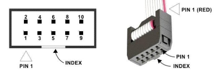
| PIN | ESP32 Connection |
| 1 | RX3 |
| 2 | SCK |
| 3 | TX3 |
| 4 | MISO |
| 5 | EXP_2 – PC3 |
| 6 | MOSI |
| 7 | EXP_1 – PC2 |
| 8 | SCL |
| 9 | GND |
| 10 | SDA |


