Product Features #
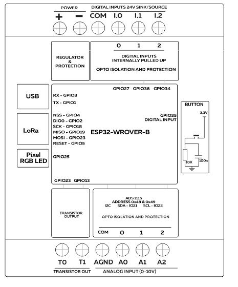
- ESP32-WROVER-B Module
- Built-in Button on the front panel
- Digital Inputs
- Analog Inputs
- Transistor Outputs
- DIN-Rail mount
Communication
- RFM95W LoRaWAN
Main #
| Range of Product | NORVI AGENT 1 |
| Product type | Programmable Node |
| Certifications | EN 61131-2:2007 EN 61010-1:2010+A1:2019 EN IEC 61010-2-201:2018 2014/30/EU- Electromagnetic Compatibility (EMC) Annex III, Part B, Module C |
| Rated supply voltage | Standard 12 – 24V DC / Low Power : 3.3 – 6V DC |
| Communication | WiFI / Bluetooth RFM95W LoRaWAN |
| Inputs and Outputs | 3 x Digital Inputs 3 x Analog Inputs: 0-10V 2 x Transistor Outputs |
| Displays and Visual Indicators | 4 X LED / Digital Inputs |
Complementary #
| Product Unified Code | NORVI AGENT 1-BT01-ES-L |
| Product Part Numbers | NORVI AGENT 1-BT01-ES-L |
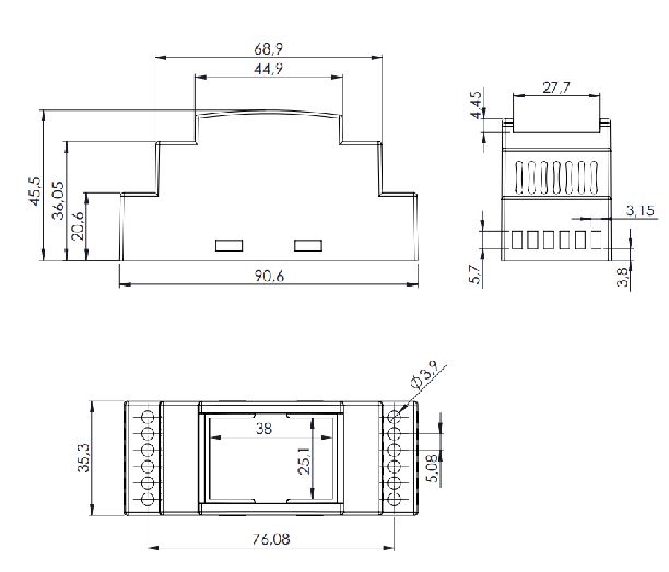
Mechanical Properties #
| Enclosure | NORVI 202 |
| Mounting / Installation Method | DIN RAIL / MOUNTING TABS |
| Terminal Type | SCREW TERMINAL |
| Terminal Arrangement | Top and Bottom |
| Length | 59.00 mm |
| Height | 86.00 mm |
| Width | 35.00 mm |
Environment #
| IP degree of protection | IP20 |
| Operating altitude | 0 – 2000 meters |
| Operating Temperature | – –10 … +85° C (14…185 °F) |
| Storage altitude | 0 – 3000 meters |
| Shock resistance | 15 gn for 11ms |
| Resistance to electrostatic discharge | 4kV on contact 8kV on air |
| Resistance to electromagnetic fields | 10 V/m (80 MHz …… 1GHz) 3 V/m (1.4 MHz …… 2 GHz) 1 V/m (2 MHz …… 3 GHz) |
Electrical Characteristics #
Grid-powered devices #
| Rated Supply Voltage (V) | 24V DC |
| Current Consumption (mA) | 400mA |
| Recommended Power Source | 1A, 24V DC |
Processing #
| SOC / MCU | ESP32-WROVER-B |
| Flash Memory | 4 MB |
| ROM | 448 KB |
| SRAM | 520 KB |
| PSRAM | 8 MB |
Built-in Buttons #
| Button 1 Pin | Digital Input GPIO35 |
Indicators #
| Module Type | WS2812 |
| Communication | One wire |
| Connection | GPIO25 |
INPUTS and OUTPUTS #
Digital Inputs #
| Number of Digital Inputs | 3 |
| Digital Input Polarity | Sink and Source |
| Digital Input Maximum Voltage | 32V DC |
| Digital Input Minimum Voltage | 18V DC |
| Maximum Switching Frequency | 1 kHZ |
| Terminal Arrangement | Digital Input 0 – GPIO27 Digital Input 1 – GPIO36 Digital Input 2 – GPIO34 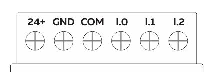 |
Analog Inputs #
| Number of Analog Inputs | 3 |
| Analog Input Measurement Range | 4-20mA |
| Analog Input Maximum Voltage | 38V DC |
| Analog to Digital Converter (ADC) | ADS1115 |
| Analog to Digital Converter (ADC) Communication | I2C |
| Analog to Digital Converter (ADC) Address | 0x48 |
| Terminal Arrangement | A0 : Analog Input 0 – ADS1115 – 0x48 – AIN0 A1 : Analog Input 1 – ADS1115 – 0x48 – AIN1 A2 : Analog Input 2 – ADS1115 – 0x48 – AIN2 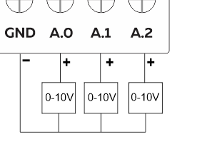 |
Transistor Outputs #
| Number of Transistor Outputs | 2 |
| Transistor Output Type | OPEN COLLECTOR |
| Maximum Sink/Source Current (mA) | 100mA |
| Maximum Applicable Voltage | 36V DC |
| Maximum Switching Frequency | 1 kHz |
| Terminal Arrangement | T.0 – GPI033 T.1 – GPI013 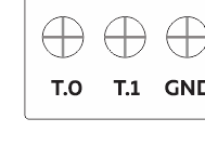 |
LoRaWAN #
| Specification | Long Range(LoRa) |
|---|---|
| RF Transceiver | RFM95W-915S2 |
| bit Rate | Up to 300 kbps |
| Link Budget | +20 dBm – 100 mW |
| RF sensitivity | -148 dBm |
| SPI MISO | GPIO19 |
| SPI MOSI | GPIO23 |
| SPI SCK | GPIO18 |
| NSS | GPIO2 |
| DIO0 | GPIO4 |
| DIO1 | GPIO15 |
| DIO2 | NOT CONNECTED |
| RESET | GPIO5 |
GPIO Map #
| GPIO | Description | Usage |
| 0 | outputs PWM signal at boot | NRST |
| 1 | USB to Serial | TX0 |
| 2 | LoRa | NSS |
| 3 | USB to Serial | RX0 |
| 4 | LoRa | DIO0 |
| 5 | LoRa | RESET |
| 13 | Output only | Transistor Output 1 |
| 14 | outputs PWM signal at boot | |
| 15 | LoRa | DIO1 |
| 16 | ||
| 17 | ||
| 18 | LoRa | SPI SCK |
| 19 | LoRa | SPI MISO |
| 22 | ||
| 23 | LoRa | SPI MOSI |
| 24 | ||
| 25 | Indicators | RGB LED |
| 26 | ||
| 27 | input only | Digital Input 0 |
| 28 | ||
| 32 | ||
| 33 | Output only | Transistor Output 0 |
| 34 | input only | Digital Input 2 |
| 35 | Button | |
| 36 | input only | Digital Input 1 |
| 37 |


