Introduction
The NORVI-IIOT, powered by the ESP32-WROOM32 microcontroller, connects to the ThingsBoard IoT platform using Wi-Fi and the MQTT protocol. It reads modbus readings(via RS485) and sends this data securely to ThingsBoard, where users can monitor real-time values through customizable dashboards. This setup allows remote access to sensor data, enabling easy monitoring and management without the need for physical device interaction.
System Architecture
The system architecture of the NORVI-IIOT device integrated with ThingsBoard is designed to enable seamless, real-time monitoring of Modbus readings using secure wireless communication. The core components and data flow are as follows:
- NORVI-IIOT Device
At the core of the system is the NORVI-IIOT device, equipped with the ESP32-WROOM32 microcontroller. This device continuously reads modbus readings from connected sensors or inputs. - Wi-Fi Connectivity
The ESP32 module establishes a Wi-Fi connection to the local network, providing internet access required for cloud communication. - MQTT Communication Protocol
Using the lightweight MQTT protocol, the NORVI-IIOT device publishes the modbus data as telemetry messages to the ThingsBoard MQTT broker. MQTT ensures reliable and efficient data transmission with minimal bandwidth consumption. - ThingsBoard IoT Platform
ThingsBoard acts as the cloud-based platform for device management, data ingestion, processing, and visualization. It receives the MQTT messages, stores telemetry data, and displays the modbus readings on customizable dashboards. - User Interface
End users can access the ThingsBoard web interface or mobile app to monitor live sensor data, configure alerts, and analyze historical measurements remotely.
ThingsBoard Setup
To successfully visualize Modbus readings from the NORVI-IIOT device, the ThingsBoard platform must be properly configured. This section outlines the key steps to set up ThingsBoard for device management and data visualization.
1. Create a ThingsBoard Account and Log In
- Register for a ThingsBoard cloud account at https://thingsboard.io or install a local ThingsBoard server.
- Log in to your ThingsBoard dashboard using your credentials.
2. Add a New Device
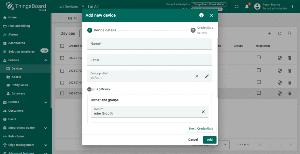
- Navigate to Devices and click + Add new device.
- Provide a meaningful name for your NORVI-IIOT device (e.g., “NORVI IIOT – Modbus RS485”).
- Save the device; this generates a unique Access Token used for MQTT authentication.
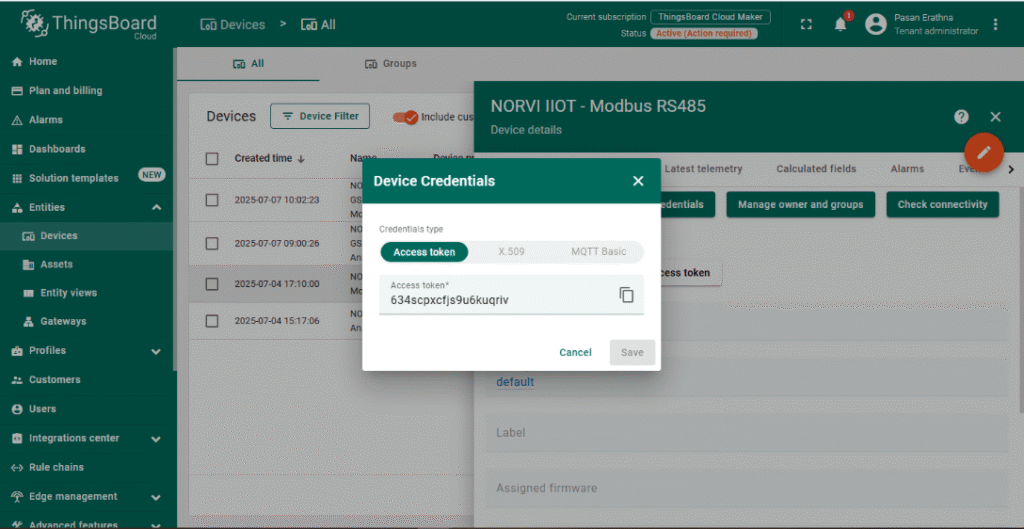
3. Configure Device Credentials
- Open the newly created device and go to the Manage credentials tab.
- Copy the Access Token; this token will be used in the ESP32 MQTT client to authenticate the device.
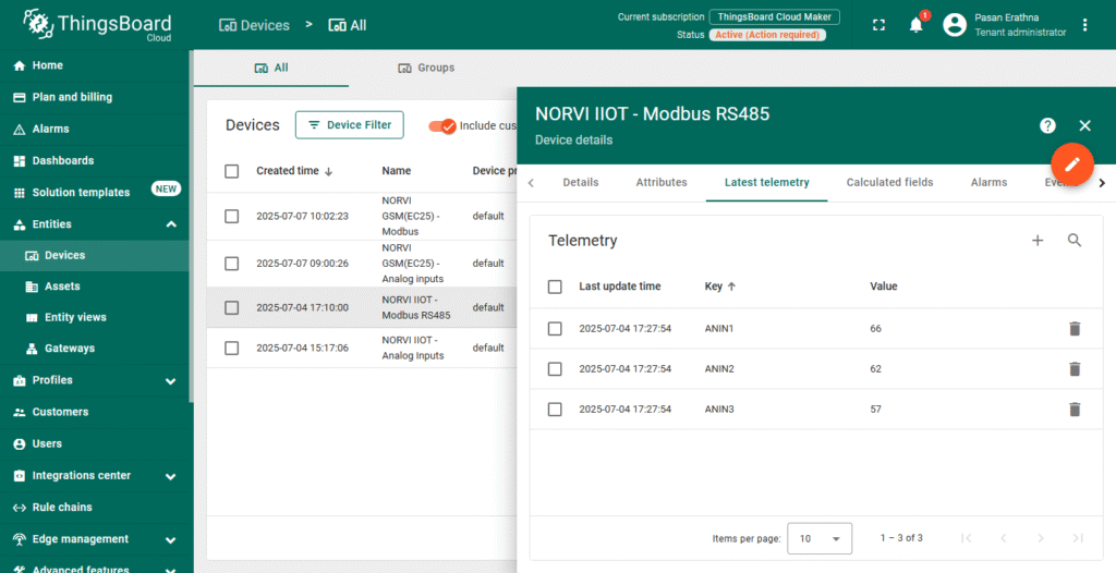
4. Set Up Telemetry Data
- ThingsBoard automatically accepts telemetry data sent via MQTT.
- Your device will publish Modbus readings as telemetry using JSON format (e.g., {“ANIN”: 66}).
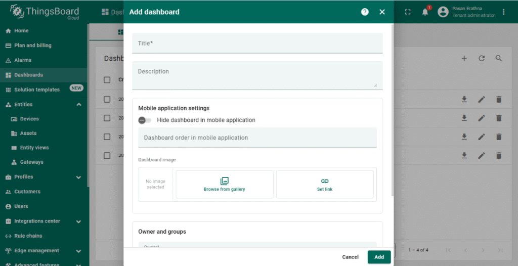
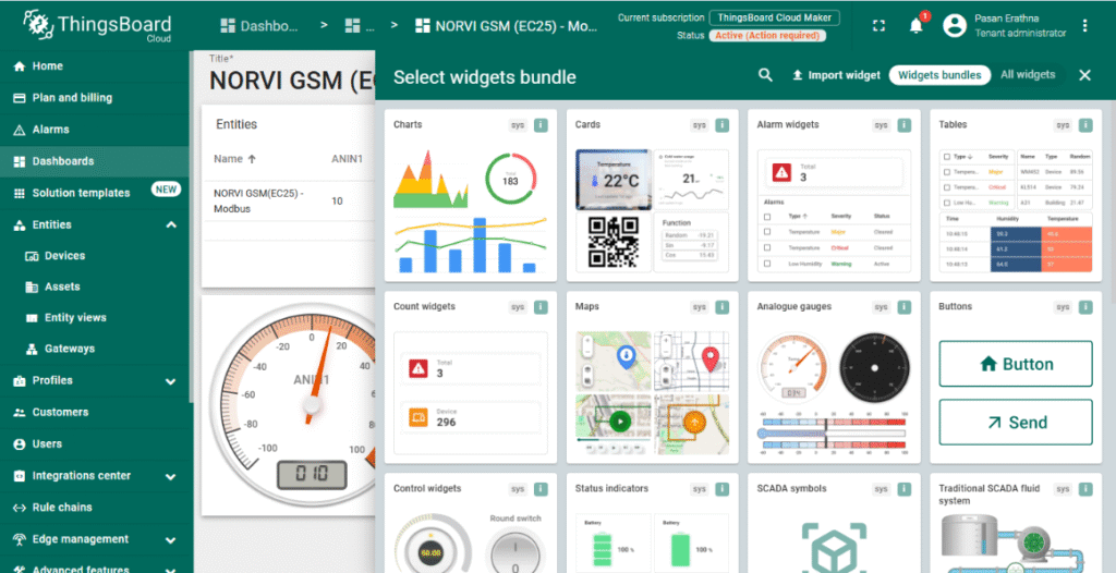
5. Create a Dashboard for Visualization
- Go to the Dashboards section and click + Add new dashboard.
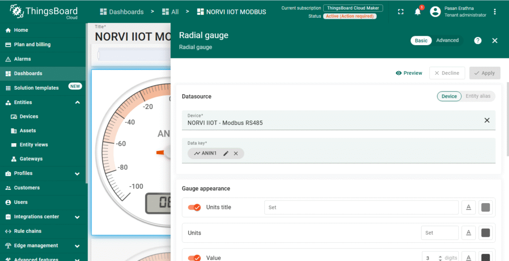
- Design a dashboard by adding widgets such as charts, gauges, or numeric displays.
- Link widgets to the NORVI-IIOT device telemetry keys (e.g., ANIN1) to visualize real-time Modbus data.
6. Optional: Set Alerts and Rules
- Configure rules to trigger alerts or actions based on input thresholds or device status.
- Use ThingsBoard’s rule engine to automate notifications or device commands.
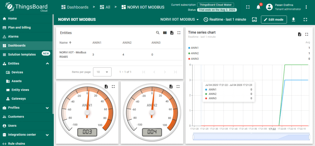
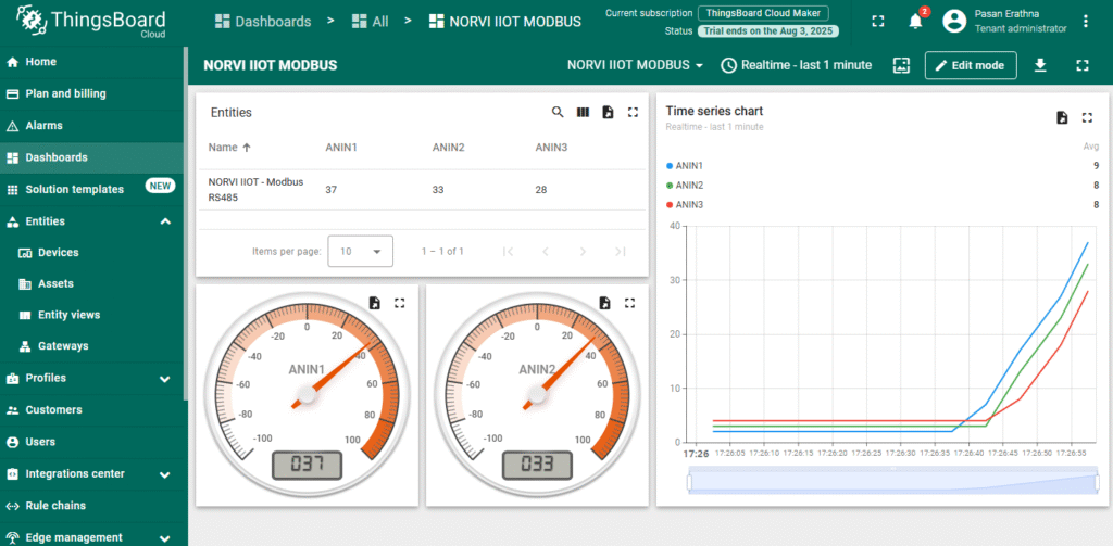
With ThingsBoard configured, the NORVI-IIOT device can securely send Modbus data over MQTT, enabling real-time monitoring and analysis through intuitive dashboards.
Software Setup
A. Install the ESP32 board in Arduino IDE:
- Go to File > Preferences.
- Go to Tools > Boards > Boards Manager, search for “ESP32”, and install.
- NORVI-with-ThingsBoard (https://github.com/IndustrialArduino/NORVI-with-ThingsBoard/tree/main/NORVII-IIOT-Modbus_RS485-ThingsBoard)
B. Install Required Libraries (Arduino):
Go to Sketch > Include Library > Manage Libraries and install:
- WiFi.h
- PubSubClient.h
- ModbusMaster.h
C. Configure the code:
Code Explanation
1. Library Inclusions and Definitions
#include <WiFi.h>
#include <PubSubClient.h>
#include <ModbusMaster.h>
#define RXD 13
#define TXD 2
#define FC  4
· WiFi.h – Connects ESP32 to Wi-Fi.
· PubSubClient.h – Handles MQTT communication with ThingsBoard.
· ModbusMaster.h – Reads data from Modbus RTU devices via RS485.
· RXD / TXD – Serial pins for RS485 communication.
· FC – Flow control pin for enabling/disabling RS485 driver.
2. Wi-Fi and ThingsBoard Credentials
const char* ssid = "username";
const char* password = "password";

const char* thingsboardServer = "thingsboard.cloud";
const int mqttPort = 1883;
const char* token = " 634scpxcfjs9u6kuqriv"; // MQTT access token from ThingsBoard device
· Wi-Fi SSID and password allow the ESP32 to connect to the local network.
· ThingsBoard server details, port (default MQTT port 1883), and the device token authenticate the device on ThingsBoard.
3. Modbus RS485 Setup
ModbusMaster node;

void preTransmission() { digitalWrite(FC, 1); }
void postTransmission() { digitalWrite(FC, 0); }
· ModbusMaster node – Modbus RTU communication object.
· preTransmission/postTransmission – Control RS485 transceiver direction (send/receive).
4. Wi-Fi Connection Function
void connectWiFi() {
  WiFi.begin(ssid, password);
  Serial.print("Connecting to WiFi");
  while (WiFi.status() != WL_CONNECTED) {
    delay(500); Serial.print(".");
  }
  Serial.println("\nWiFi connected!");
}
5. MQTT Connection Function
void connectMQTT() {
  while (!client.connected()) {
    Serial.print("Connecting to ThingsBoard MQTT...");
    if (client.connect("ESP32Client", token, NULL)) {
      Serial.println("connected!");
    } else {
      Serial.print("failed with state ");
      Serial.println(client.state());
      delay(2000);
    }
  }
}
6. Sending Telemetry Data
6. Sending Telemetry Data

void sendTelemetry() {

  uint8_t value;
  uint8_t IN1, IN2, IN3, IN4;
  value = node.readHoldingRegisters(0x40001, 3);

  IN1 = node.getResponseBuffer(0x00);
  IN2 = node.getResponseBuffer(0x01);
  IN3 = node.getResponseBuffer(0x02);

  Serial.print("\n");
  Serial.print(" ANIN1 : ");
  Serial.print(IN1);
  Serial.print(" ANIN2 : ");
  Serial.print(IN2);
  Serial.print(" ANIN3 : ");
  Serial.print(IN3);
  Serial.print("\n");
  delay(500);


  String payload = "{\"ANIN1\":";
  payload += IN1;
  payload += ", \"ANIN2\":";
  payload += IN2;
  payload += ", \"ANIN3\":";
  payload += IN3;
  payload += "}";

  Serial.print("Publishing: ");
  Serial.println(payload);

  client.publish("v1/devices/me/telemetry", payload.c_str());
}
· Reads 3 holding registers starting at address 0x40001.
· Extracts each register value (IN1, IN2, IN3)
· Constructs a JSON string payload with modbus readings (ANIN1 to ANIN3).
· Publishes telemetry data to ThingsBoard MQTT topic “v1/devices/me/telemetry”.
7. Setup Function
void setup() {
  Serial.begin(9600);
  delay(100);
  connectWiFi();
  delay(1000);
  client.setServer(thingsboardServer, mqttPort);
  delay(1000);

  pinMode(FC, OUTPUT);
  digitalWrite(FC, 0);

  Serial1.begin(9600, SERIAL_8N1, RXD, TXD);

  node.begin(1, Serial1);                           //Slave ID as 1
  node.preTransmission(preTransmission);
  delay(10);
  node.postTransmission(postTransmission);
}
· Initializes serial communication for debug output.
· Connects to Wi-Fi.
· Configures MQTT server.
· Initializes RS485 pins, and Modbus communication.
8. Main Loop
void loop() {
  if (!client.connected()) {
    connectMQTT();
  }

  client.loop();

  if (millis() - lastSend > 5000) {
    lastSend = millis();
    sendTelemetry();
  }
}
· Keeps MQTT connection alive, reconnects if disconnected.
· Calls client.loop() to maintain MQTT client state.
· Sends telemetry every 5 seconds.
Testing Setup
1.Upload the Firmware
Compile and upload the firmware to the ESP32 and check the serial monitor output and verify that device is connected to the Wifi and ThingsBoard MQTT.
2. Expected Outputs
ESP32 logs network connection and update status.
Check ThingsBoard dashboard to confirm it displays correct Modbus readings.
Common Issues & Fixes
| Issue | Possible Cause | Solution |
| Wi-Fi not connecting | Incorrect SSID or password; weak signal | Verify credentials in code, ensure router is on and within range |
| MQTT connection failure | Wrong server/port; invalid Access Token | Check ThingsBoard server address and port; confirm Access Token matches device in ThingsBoard |
| No Modbus data received | Wrong slave ID or register address in code | Verify the Modbus slave ID and register addresses with your device’s documentation and update node.begin() and readHoldingRegisters() accordingly. |
| Data updates delayed or missing | Long send interval; Wi-Fi dropouts | Reduce telemetry interval in code; check Wi-Fi stability |
| All values show 0 | RS485 wiring reversed (A/B swapped) | Swap the A/B lines between NORVI-IIOT and Modbus device. |
| No Modbus readings on dashboard | Widget keys don’t match telemetry keys | Ensure ThingsBoard widget keys match JSON keys (ANIN1, etc.) sent by device |


