The NORVI AI Optic camera module stands out as a versatile device designed for various imaging applications. Featuring a built-in display, users can easily preview captured images in real-time. Equipped with the Camera, this module delivers high-quality images, making it suitable for computer vision.
Additionally, its microSD card support allows for convenient storage and transfer of captured media files, ensuring ample storage space for extended usage. With an external trigger feature, users can synchronize image capture with external events or signals, expanding its utility in diverse scenarios.
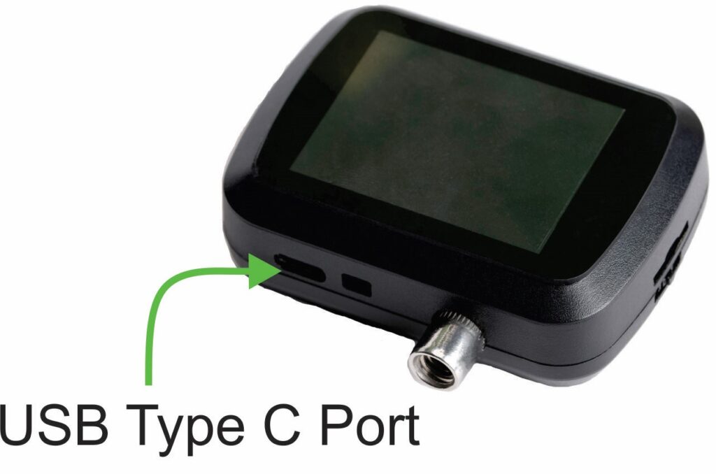
The inclusion of a C type USB Port serves a dual purpose, facilitating both battery charging and programming tasks, making the NORVI AI Optic camera module a comprehensive solution for computer vision applications.
| Board | ESP32-S3 Dev Module |
| Flash Size | 16 |
| Flash mode | QIO 80MHz |
| USB CDC on Boot | Enabled |
| USB firmware MSC on boot | Disabled |
| USB DFU on boot | Disabled |
| Upload mode | UART0 / Hardware CDC |
| PSRAM | OPI PSRAM |
| Programming Port | C type USB |
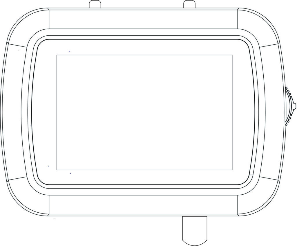
DEVICE POWER UP AND POWER DOWN #
The POWER UP and POWER DOWN mechanism is controlled by the battery managing system and its totally independent from the user program on the device.
Power Up #
Push the rotary switch for about 5 seconds and release then the device will power ON.
Power Down #
Push and release the rotary switch for about 15 seconds and the device will power down.
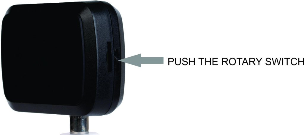
ROTARY SWITCH #
The rotary switch allows users to adjust the parameters or build a UI with UP / DOWN and Push Actions of the switch.

Functions of the switch,
- Push : Acts as a push button, used to power on and off the device.
- Rotation: Detects the direction and amount of rotation, used to navigate the settings of the device.
GPIOs for Rotary Switch #
| Button_up | Connected to GPIO0. Can be used for adjusting parameters or a custom menu. This pin detects when the rotary switch is rotated upwards. |
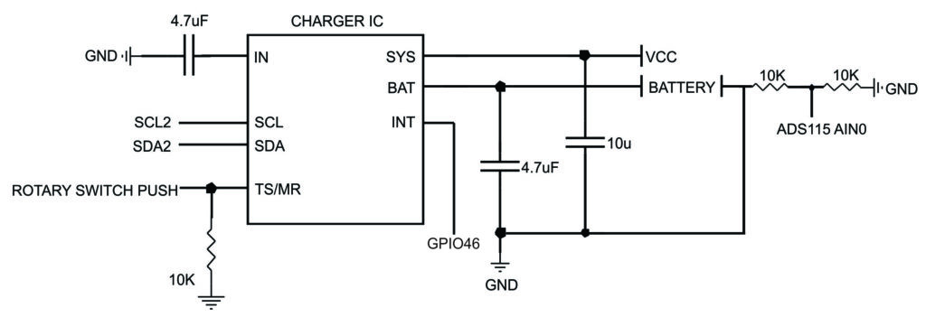
| Push | Connected to Battery manager, facilitates power ON and Power OFF, by long press. Short press sends a pulse to the ESP32-S3 through the GPIO 46. |
| Button_down | This pin detects when the rotary switch is rotated downwards. Via PCA9536DGKR – P2 SCL2 – GPIO14 SDA2 – GPIO1 |

USB PORT #
The USB port on this device uses a USB Type-C connector. The device has a rechargeable battery, and the USB port can be used to charge the battery. This is used for programming the ESP32-S3 chip and its connected to the USB port of the ESP32-S3.
GPIOs for USB Port #
| DP1/DP2 (GPIO20) | These pins are used for the positive data lines of the USB differential pair, carrying data to and from the device. |
| DN1/DN2 (GPIO19) | These pins are used for the negative data lines of the USB differential pair, completing the data transmission circuit. |
MICROSD CARD SUPPORT #
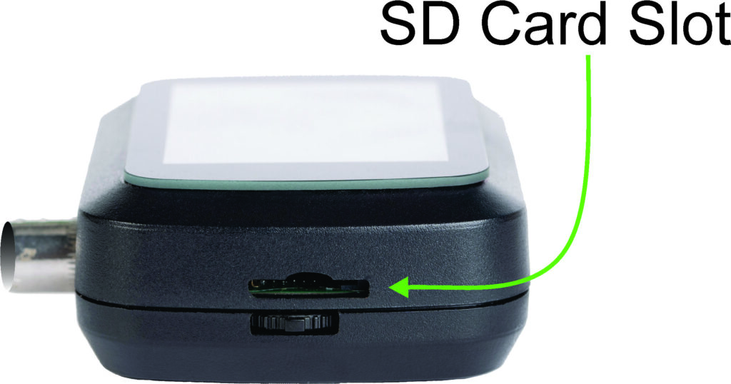
The MEM2067 microSD card module provides storage capabilities to the camera. This module supports microSD cards and uses the Serial Peripheral Interface (SPI) for communication.
GPIOs for Micro SD Card #
| CMD (GPIO38): | This pin is used for sending commands to the microSD card. |
| CLK (GPIO39) | This pin provides the clock signal necessary for synchronizing the data transfer between the microcontroller and the microSD card. |
| DATA (GPIO40) | This pin is used for data transmission between the microSD card and the microcontroller. |
LED FLASHLIGHTS #

NORVI AI Optic has high-power LEDs designed to provide bright, white light with high efficiency. The Flash Lights are controlled via the IO Expander PCA9536DGKR. The communication with the IO Expander is done using the I2C protocol.
| LED_FLASH (LED FlashLight) | Via PCA9536DGKR – P1 |

TRIGGER BUTTON AND RESET #
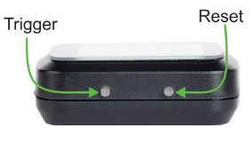
These buttons are used to control the operating conditions of the device, the reset button is used to reset the system and the trigger button is used to take photos.
Press and Hold: Press and hold the reset button for a few seconds until the device resets.
Press and Hold: The trigger button allows taking photos by pressing and holding it.
DIGITAL INPUT (EXTERNAL TRIGGER) #
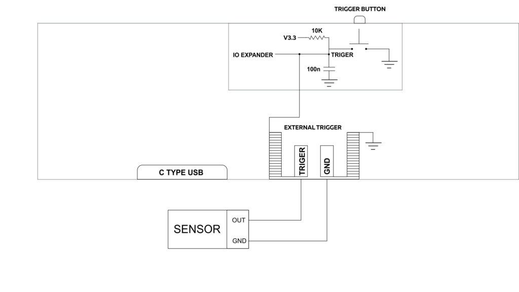
This product is a compact camera module with an internal trigger and an external trigger for capturing photos. The internal trigger allows pictures to be taken using an onboard button. Additionally, the module supports digital inputs for an external trigger.
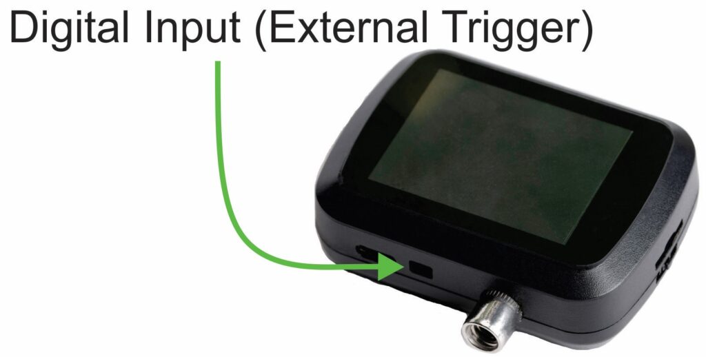
An external sensor can be connected to the digital input terminal and photos can be taken without having to use the internal trigger button.
SETTING ESP32 S3 TO BOOT MODE #
If unable to upload code Connect the device to a computer via a USB Type-C cable, set the device to boot mode, by pressing the reset button while holding the joystick switch up .


UNDERSTANDING THE PROGRAM #
This code is designed for the ESP32-S3 microcontroller to initialize and control a camera module, display images on a TFT screen, and manage various parameters and hardware components via I2C devices.
The code integrates camera control, image display, and various hardware management functionalities. It initializes components, captures and displays images, and provides a user interface for adjusting camera settings. The loop function ensures continuous operation, updating settings, reading status, and controlling peripherals as needed.
Step into the example program by clicking here.
Include Libraries:
Various libraries are included, such as esp_camera, SPI, TFT_eSPI, TJpg_Decoder, Wire, PCA9536D, and Adafruit_ADS1X15.
Download the required libraries from here.
Defined variables and I2C detection:
The I2C devices connected to the system are detected and their addresses are printed out and Included structures for storing parameters, flags, and pin assignments.
#define BQ25180_ADDR 0x6A  // I2C address of the bq25180
#define CGCTRL_REG_ADDR 0x4
#define IC_CTRL  0x7
#define SHIP_RST 0x9
#define SYS_REG 0xA
#define TMR_ILIM 0x8

#define IO_TRIGGER 0
#define IO_LED_FLASH 1
#define IO_BUTTON_DOWN 2
#define IO_BUTTON_UP 0
#define IO_SWITCH 46
Parameter Initialization:
Initial values for different camera parameters are set within an array.
Adafruit_ADS1115 ads;
PCA9536 io;

TFT_eSPI tft = TFT_eSPI();
OV5640 ov5640 = OV5640();
Parameter Structure:
A structure called Parameter is defined as a main menu to store the label, value, minimum, and maximum values for camera parameters.
unsigned int menu_index=0;unsigned int value_change_flag=0;
struct Parameter {
    const char* label;
    int value;
    int minValue;
    int maxValue;};
Parameter parameters[] = {...};
Array of Parameters:
An array of Parameter structures where each element represents a specific parameter. Each element of the array consists of a label (name), current value, minimum allowed value, and maximum allowed value for the corresponding parameter.
Parameter parameters[] = {
    {"Brightness", 0, -2, 2},
    {"Contrast", 2, -2, 2},
    {"Saturation", 0, -2, 2},
    {"Special Effect", 0, 0, 6},
    {"White Balance", 1, 0, 1},
    {"AWB Gain", 1, 0, 1},
    {"WB Mode", 0, 0, 4},
    {"Exposure Control", 0, 0, 1},
    {"AEC2", 1, 0, 1},
    {"AE Level", 2, -2, 2},
    {"AEC Value", 800, 0, 1200},
    {"Gain Control", 1, 0, 1},
    {"AGC Gain", 0, 0, 30},
    {"Gain Ceiling", 6, 0, 6},
    {"BPC", 1, 0, 1},
    {"WPC", 1, 0, 1},
    {"RAW GMA", 1, 0, 1},
    {"LENC", 1, 0, 1},
    {"H-Mirror", 1, 0, 1},
    {"V-Flip", 0, 0, 1},
    {"DCW", 1, 0, 1},
    {"Color Bar", 0, 0, 1},
    {"Flash", 0, 0, 2},
    {"SYSTEM", 0, 0, 2}
};
Integer variable representing the saturation parameters and the AEC (Automatic Exposure Control) parameters.
int param_saturation=0,param_saturation_max=2,param_saturation_min=-2;
int param_aec=0,param_aec_max=1200,param_aec_min=0;
Variables used for various triggers and switches.
unsigned int TRIGGER, SWITCH, B_UP, B_DOWN, TRIGGER_S, SWITCH_S, B_UP_S, B_DOWN_S;
unsigned int V_DELAY;
volatile int count = 0;
An Interrupt Service Routine (ISR) triggered by the joystick switch push. This is used to scroll through the parameters of the menu.
void IRAM_ATTR handleInterrupt() {
  // Increase the count when interrupt occurs
  menu_index++;
  if(menu_index>23)menu_index=0;
}
TFT LCD DISPLAY #
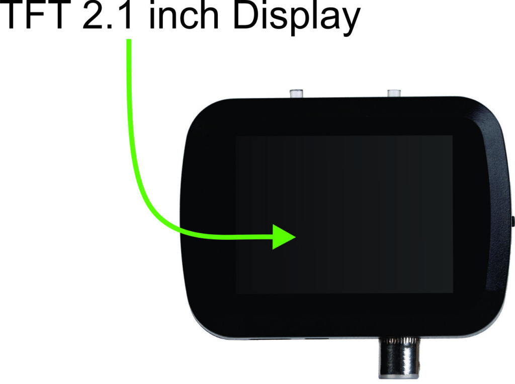
| Display Driver | ST7789 |
| Display Type | TFT LCD Display |
| Display Size | 2.1 inches |
| Resolution | 240×320 Pixels |
GPIO for the TFT Display #
| SCL (GPIO14) | Serial Clock Line |
| SDA (GPIO1) | Serial Data Line |
| DSP_CS (GPIO36) | Activates the display for communication. |
| RS (GPIO37) | Differentiates between command and data registers. |
| DSP_RST (GPIO48) | Resets the display to a known state. |
| MOSI (GPIO47) | Used in SPI communication. |
| SCLK (GPIO21) | Provides the clock signal for SPI communication. |
Programming the TFT Display #
This code initializes the display and JPEG decoder, sets up a callback for image rendering, and defines a function to display menu information and sensor readings on the TFT display.
displayInit Function
Initializes a TFT display and configures the JPEG decoder. It starts by initializing the display hardware and setting the rotation to landscape mode. Then, it fills the screen with a white background and configures the decoder to display JPEG images at their original size. Additionally, it adjusts the byte order for correct image rendering and sets a callback function to handle displaying decoded images on the screen.
void displayInit(){
  tft.begin();
  tft.setRotation(1);
  tft.fillScreen(TFT_WHITE);
  TJpgDec.setJpgScale(1);
  TJpgDec.setSwapBytes(true);
  TJpgDec.setCallback(tft_output);
}
tft_output Function
The “tft_output” function is a callback for the JPEG decoder, used to display JPEG images on a TFT display. It checks if the y-coordinate is within the display height; if not, it returns 0. Otherwise, it draws the image at the specified coordinates using the provided image data and returns 1 to signify successful rendering.
bool tft_output(int16_t x, int16_t y, uint16_t w, uint16_t h, uint16_t* bitmap){
  if( y>= tft.height()) return 0;
  tft.pushImage(x, y, w, h, bitmap);
  return 1;
}
display_menu Function
The “display_menu” function updates the TFT display to show a menu at the bottom along with additional information. It first draws a black rectangle at the bottom to serve as the menu background. Then, it sets the cursor position and text properties for displaying menu items. It prints the label and value of the current menu item within the rectangle. Additionally, it sets the cursor to the top left corner and prints a voltage value calculated from a variable called volts0 multiplied by 2 at the top of the screen.
void display_menu(){

  tft.fillRect(0, tft.height() - 30, tft.width(), 30, TFT_BLACK);
  tft.setCursor(10, tft.height() - 30 + 5); // Adjust the coordinates as needed
  tft.setTextColor(TFT_WHITE); // Set text color
  tft.setTextSize(2); // Set text size
  tft.print(parameters[menu_index].label);
  tft.print(" : ");
  tft.print(parameters[menu_index].value);
  tft.setCursor(10, 10); // Adjust the coordinates as needed
  tft.setTextColor(TFT_WHITE); // Set text color
  tft.setTextSize(2); // Set text size
  tft.print(volts0*2);
}
OV5640-AF CAMERA #
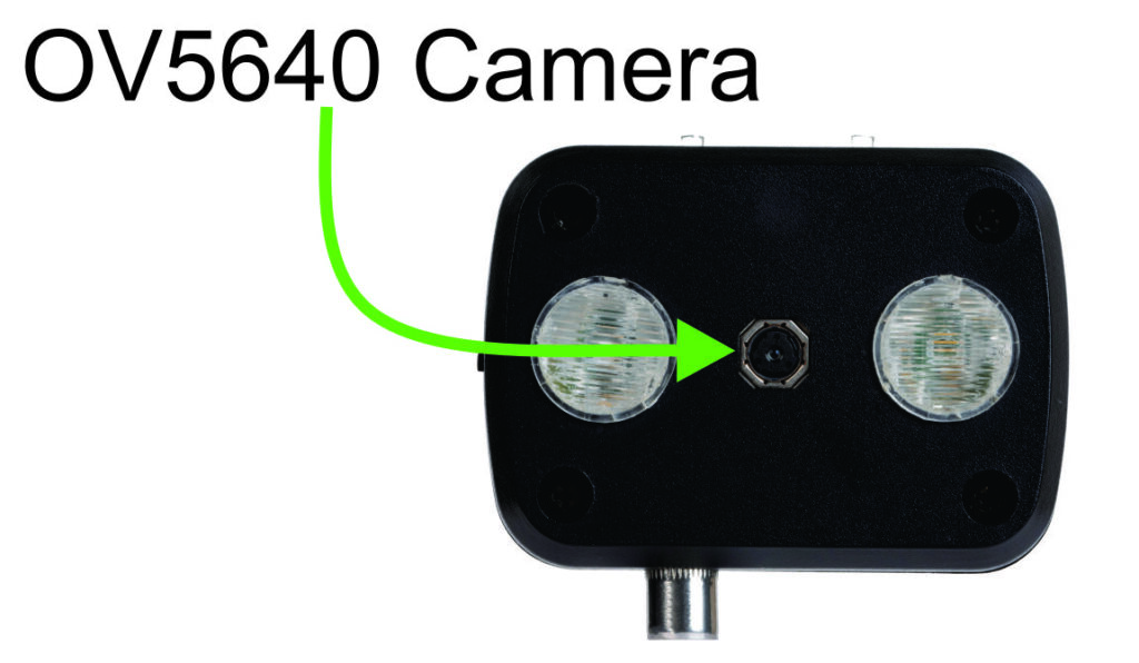
The OV5640-AF camera module includes an integrated auto-focus feature with a resolution of 5 megapixels.
GPIOs for OV5640 camera #
| I2C Communication | SDA (GPIO4) | I2C data line. |
| SCL (GPIO5) | I2C clock line. | |
| Synchronization Signals | VSYNC (GPIO6) | Indicates the start of a new frame. |
| HREF (GPIO7) | Indicates the start of a new line within a frame. | |
| Clock Signals | MCLK (GPIO15) | Provides the master clock signal to the camera. |
| PCLK (GPIO13) | Provides the pixel clock signal, which synchronizes the data output from the camera. | |
| Power | GPIO41 | Supplies power to the camera module. |
| Reset | GPIO42 | Used to reset the camera module. |
| Data Lines | D2 (GPIO11) | Used for the parallel data output from the camera. |
| D3 (GPIO9) | ||
| D4 (GPIO8) | ||
| D5 (GPIO10) | ||
| D6 (GPIO12) | ||
| D7 (GPIO18) | ||
| D8 (GPIO17) | ||
| D9 (GPIO16) |
Programming the OV5640 Camera #
This code allows for configuring and managing a camera module, capturing and displaying images, and dynamically adjusting camera settings based on user-defined parameters.
cameraInit Function
The “cameraInit” function sets up and initializes a camera module, defining settings such as resolution and format. It adjusts settings based on available memory and chosen format, then initializes the camera and configures sensor settings.
void cameraInit(){
  camera_config_t config;
  config.ledc_channel = LEDC_CHANNEL_0;config.ledc_timer = LEDC_TIMER_0;
  config.pin_d0 = Y2_GPIO_NUM;config.pin_d1 = Y3_GPIO_NUM;
  config.pin_d2 = Y4_GPIO_NUM;config.pin_d3 = Y5_GPIO_NUM;
  config.pin_d4 = Y6_GPIO_NUM;config.pin_d5 = Y7_GPIO_NUM;
  config.pin_d6 = Y8_GPIO_NUM;config.pin_d7 = Y9_GPIO_NUM;
  config.pin_xclk = XCLK_GPIO_NUM;config.pin_pclk = PCLK_GPIO_NUM;
  config.pin_vsync = VSYNC_GPIO_NUM;config.pin_href = HREF_GPIO_NUM;
  config.pin_sccb_sda = SIOD_GPIO_NUM;config.pin_sccb_scl = SIOC_GPIO_NUM;
  config.pin_pwdn = PWDN_GPIO_NUM;config.pin_reset = RESET_GPIO_NUM;
  config.xclk_freq_hz = 20000000;config.frame_size = FRAMESIZE_QVGA;
  config.pixel_format = PIXFORMAT_JPEG; // for streaming
  config.grab_mode = CAMERA_GRAB_WHEN_EMPTY;
  config.fb_location = CAMERA_FB_IN_PSRAM;
  config.jpeg_quality = 10;config.fb_count = 1;
 if(config.pixel_format == PIXFORMAT_JPEG){
    if(psramFound()){
      config.jpeg_quality = 5;
      config.fb_count = 2;config.grab_mode = CAMERA_GRAB_LATEST;
    } else {
      // Limit the frame size when PSRAM is not available
     config.frame_size = FRAMESIZE_QVGA;config.fb_location = CAMERA_FB_IN_DRAM;
    }
  } else {
    // Best option for face detection/recognition
    config.frame_size = FRAMESIZE_240X240;
#if CONFIG_IDF_TARGET_ESP32S3
    config.fb_count = 2;
#endif
  }
  esp_err_t err = esp_camera_init(&config);
  if (err != ESP_OK) {
    Serial.printf("Camera init failed with error 0x%x", err);
    return;
  }

sensor_t * s = esp_camera_sensor_get();
    s->set_brightness(s, 0);     // -2 to 2
    s->set_contrast(s, 2);       // -2 to 2
    s->set_saturation(s, 0);     // -2 to 2
    s->set_special_effect(s, 0); // 0 to 6 (0 - No Effect, 1 - Negative, 2 - Grayscale, 3 - Red Tint, 4 - Green Tint, 5 - Blue Tint, 6 - Sepia)
    s->set_whitebal(s, 1);       // 0 = disable , 1 = enable
    s->set_awb_gain(s, 1);       // 0 = disable , 1 = enable
    s->set_wb_mode(s, 0);        // 0 to 4 - if awb_gain enabled (0 - Auto, 1 - Sunny, 2 - Cloudy, 3 - Office, 4 - Home)
    s->set_exposure_ctrl(s, 0);  // 0 = disable , 1 = enable
    s->set_aec2(s, 1);           // 0 = disable , 1 = enable
    s->set_ae_level(s, 2);       // -2 to 2
    s->set_aec_value(s, 800);    // 0 to 1200
    s->set_gain_ctrl(s, 1);      // 0 = disable , 1 = enable
    s->set_agc_gain(s, 0);       // 0 to 30
    s->set_gainceiling(s, (gainceiling_t)6);  // 0 to 6
    s->set_bpc(s, 1);            // 0 = disable , 1 = enable
    s->set_wpc(s, 1);            // 0 = disable , 1 = enable
    s->set_raw_gma(s, 1);        // 0 = disable , 1 = enable
    s->set_lenc(s, 1);           // 0 = disable , 1 = enable
    s->set_hmirror(s, 1);        // 0 = disable , 1 = enable
    s->set_vflip(s, 0);          // 0 = disable , 1 = enable
    s->set_dcw(s, 1);            // 0 = disable , 1 = enable
    s->set_colorbar(s, 0);       // 0 = disable , 1 = enable
}
showingImage Function
Captures an image from the camera by obtaining a frame buffer (fb) using esp_camera_fb_get(). If the buffer is not available or the format is not JPEG, it prints an error message. Otherwise, it displays the JPEG image on the screen using T JpegDec.draw Jpg(), specifying the coordinates and image data. Finally, it returns the frame buffer to the camera driver.
void showingImage(){
  camera_fb_t* fb = esp_camera_fb_get();
  if(!fb || fb->format != PIXFORMAT_JPEG){
    Serial.println("Camera Capture Failed!");
  }else{
   // Serial.println("Camera Image to Display Here!");
   int textAreaHeight = 30; // Adjust this according to your text size and position
    TJpgDec.drawJpg(0, 0, (const uint8_t*)fb->buf, fb->len);
    // Draw a black rectangle at the bottom of the display
  }
  esp_camera_fb_return(fb);
}
update_setting Function
Modifies camera settings using values from the parameters array if the value_change_flag is set. It accesses the sensor object and adjusts parameters like brightness, contrast, and white balance based on the array values. After updating, it resets the flag and introduces a delay for the settings to take effect.
void update_setting(){
  if(value_change_flag==1){
    sensor_t * s = esp_camera_sensor_get();
    s->set_brightness(s, parameters[0].value);     // -2 to 2
    s->set_contrast(s, parameters[1].value);       // -2 to 2
    s->set_saturation(s, parameters[2].value);     // -2 to 2
  s->set_special_effect(s, parameters[3].value); // 0 to 6 (0-NoEffect,1- Negative,2-Grayscale, 3 - Red Tint, 4 - Green Tint, 5 - Blue Tint, 6 - Sepia)
    s->set_whitebal(s, parameters[4].value);       // 0 = disable , 1 = enable
    s->set_awb_gain(s, parameters[5].value);       // 0 = disable , 1 = enable
   s->set_wb_mode(s, parameters[6].value);      // 0 to 4 - if awb_gain enabled (0 - Auto, 1 - Sunny, 2 - Cloudy, 3 - Office, 4 - Home)
    s->set_exposure_ctrl(s, parameters[7].value);  // 0 = disable , 1 = enable
    s->set_aec2(s, parameters[8].value);           // 0 = disable , 1 = enable
    s->set_ae_level(s, parameters[9].value);       // -2 to 2
    s->set_aec_value(s, parameters[10].value);    // 0 to 1200
    s->set_gain_ctrl(s, parameters[11].value);      // 0 = disable , 1 = enable
    s->set_agc_gain(s, parameters[12].value);       // 0 to 30
    s->set_gainceiling(s, (gainceiling_t)parameters[13].value);  // 0 to 6
    s->set_bpc(s, parameters[14].value);            // 0 = disable , 1 = enable
    s->set_wpc(s, parameters[15].value);            // 0 = disable , 1 = enable
    s->set_raw_gma(s, parameters[16].value);        // 0 = disable , 1 = enable
    s->set_lenc(s, parameters[17].value);           // 0 = disable , 1 = enable
    s->set_hmirror(s, 1);        // 0 = disable , 1 = enable
    s->set_vflip(s, 0);          // 0 = disable , 1 = enable
    s->set_dcw(s, parameters[20].value);            // 0 = disable , 1 = enable
    s->set_colorbar(s, parameters[21].value);       // 0 = disable , 1 = enable
 value_change_flag=0;
 delay(300);
 }
}
RECHARGEABLE BATTERY AND THE CHARGING IC #
The HY 602550 rechargeable battery is a crucial component for the camera module, providing the necessary power for its operation.
| Battery Type | Lithium-ion, Lithium Polymer |
| Charging Voltage | 5V |
| Capacity | 600mAh |
The BQ25180YBGR is a linear battery charger IC used to charge the lithium ion rechargeable battery of the camera module. It supports a nominal battery voltage of 3.7V with a charging voltage of 4.2V and an output current of up to 1A, suitable for batteries with a rated capacity of 600mAh.
| BAT | ADS1115 AIN0 |
| INT | GPIO46 |
Programming the Battery Charger IC #
This code segment primarily deals with reading and writing registers of an I2C device, specifically the BQ25180 battery charger, and configuring its settings.
Reads a specific register value from the BQ25180 battery charger. It begins by starting a transmission to the device, specifying its address. Then, it writes the register address to be read. After initiating the transmission, it requests one byte of data from the device. If data is available, it reads the byte and returns its value.
unsigned int read_register(byte reg_addr){
  byte registerValue;
  Wire.beginTransmission(BQ25180_ADDR);
  Wire.write(reg_addr); // Register address to read
  Wire.endTransmission(false); // Restart
  Wire.requestFrom(BQ25180_ADDR, 1); // Request 1 byte from the device

  if (Wire.available()) {
    registerValue = Wire.read(); // Read the byte
  } else {
    Serial.println("Error: No response from device");
  }
  return registerValue;
}
write_register Function:
Writes a value to a specified register of the BQ25180 battery charger. It starts by initiating a transmission to the device, specifying its address. Then, it writes the register address and the value to be written. Finally, it ends the transmission.
void write_register(byte reg_add, byte reg_val){
  Wire.beginTransmission(BQ25180_ADDR);
  Wire.write(reg_add);   // Address of register to write to
  Wire.write(reg_val);       // Data to write
  Wire.endTransmission(); }
read_status Function:
Reads status registers from the BQ25180 battery charger, extracts specific bits using bitwise operations, and prints the status of each bit. It reads two status registers, extracts relevant bits indicating charger statuses like charging, temperature, and voltage, and prints them using Serial.print.
void read_status(){
  byte status_reg0, status_reg1;
  int bits56, bits34;
  bool bit0, bit1, bit2, bit3, bit4, bit5, bit6, bit7;
  status_reg0 = read_register(0x00);status_reg1 = read_register(0x01);
  bits56 = ((status_reg0 >> 5) & 0b00000011);
  bit0 = (status_reg0 & 0b00000001) > 0;
  bit1 = (status_reg0 & 0b00000010) > 0;
  bit2 = (status_reg0 & 0b00000100) > 0;
  bit3 = (status_reg0 & 0b00001000) > 0;
  bit4 = (status_reg0 & 0b00010000) > 0;
  bit5 = (bits56 & 0b00000001) > 0;
  bit6 = (bits56 & 0b00000010) > 0;
  bit7 = (status_reg0 & 0b10000000) > 0;

  Serial.print("VIN:");Serial.print(bit0);Serial.print("THM:");
  Serial.print(bit1);Serial.print("DPM:");Serial.print(bit2);
  Serial.print("PPM:");Serial.print(bit3);Serial.print("ILIM:");
  Serial.print(bit4);Serial.print("CHG:);Serial.print(bits56);
  Serial.print(" TS: ");Serial.print(bit7);

  bits34 = ((status_reg1 >> 3) & 0b00000011);
  bit0 = (status_reg1 & 0b00000001) > 0;
  bit1 = (status_reg1 & 0b00000010) > 0;
  bit2 = (status_reg1 & 0b00000100) > 0;
  bit3 = (status_reg1 & 0b00001000) > 0;
  bit4 = (status_reg1 & 0b00010000) > 0;
  bit5 = (status_reg1 & 0b00100000) > 0;
  bit6 = (status_reg1 & 0b01000000) > 0;
  bit7 = (status_reg1 & 0b10000000) > 0;

  Serial.print("WK2:");Serial.print(bit0);Serial.print("WK1:");
  Serial.print(bit1);Serial.print(" SFC: ");Serial.print(bit2);
  Serial.print("TS:");Serial.print(bits34);Serial.print("BUV:");
  Serial.print(bit6);Serial.print(" IOV: ");Serial.println(bit7); }
config_charger Function:
Configures settings of the BQ25180 battery charger by writing values to specific registers. It adjusts the charging current, disables temperature sensor auto mode, and sets the push-button long press time. Each configuration step is followed by a corresponding Serial.println statement for debugging and monitoring purposes.
void config_charger(){
  write_register(CGCTRL_REG_ADDR, 0x50);
  Serial.println("Charging Current Set to 530mA");
  delay(100);
  write_register(IC_CTRL, 0x04);
  Serial.println("Disable TS Auto");
  write_register(TMR_ILIM, 0x0D);
  Serial.println("Push button Long Press to 5s");
  delay(100);
  write_register(SYS_REG, 0x40);
  Serial.println("Writing to SYS CONTROL");
}
config_sys Function:
Dynamically configures system settings based on a parameter’s value. If the specified parameter’s value is 1, it writes a specific value to the system control register using a provided function. Otherwise, it writes a different value. This enables flexible configuration based on user-defined parameters.
void config_sys(){
  if(parameters[23].value==1)write_register(SYS_REG, 0x48);
  else write_register(SYS_REG, 0x40);
  }
DEVICE MOUNTING #
Proper mounting of a camera is essential to ensure steady and stable image capture. The camera module includes an in-built mounting bracket, allowing it to be attached to a tripod or stand.


