Programming #
The NORVI EC-M11-EG-C5-B95 has a mini USB port for serial connection with the SoC for programming. Any ESP32-supported programming IDE can be used to program the controller. Follow this guide to programming NORVI ESP32-based controllers with the Arduino IDE.
SoC: ESP32-WROOM32
Programming Port: USB UART
8-pin Connector and wire harness #
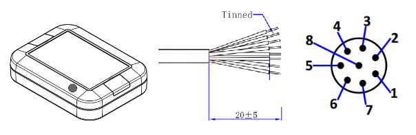
Pin Description #
| 8P Male | Wire color | I/O Configuration |
| 1 | White | SCL |
| 2 | Brown | SDA |
| 3 | Green | – |
| 4 | Yellow | – |
| 5 | Gray | 3.3V+ / 5V+ |
| 6 | Pink | – |
| 7 | Blue | Power+ |
| 8 | Red | Power- |
I2C Communication #
| IC Type | ADS 1115 |
| Module Address | 0x49 |
| SDA | GPIO16 |
| SCL | GPIO17 |
Programming I2C Communication #
#include <Wire.h>
// Define the I2C device address
#define DEVICE_ADDRESS 0x49

void setup() {
  Wire.begin(16, 17);  // SDA on GPIO16, SCL on GPIO17
  Serial.begin(115200);
}

void loop() {
  // Write data to the I2C device
  Wire.beginTransmission(DEVICE_ADDRESS);
  Wire.write(0x01);  // Replace with your data
  Wire.write(0x02);
  Wire.write(0x03);
  Wire.endTransmission();
  delay(100);
  // Read data from the I2C device
  Wire.requestFrom(DEVICE_ADDRESS, 3);  // 3 bytes of data
  if (Wire.available() >= 3) {
    byte data1 = Wire.read();
    byte data2 = Wire.read();
    byte data3 = Wire.read();
    Serial.print("Read Data: ");
    Serial.print(data1, HEX);
    Serial.print(" ");
    Serial.print(data2, HEX);
    Serial.print(" ");
    Serial.println(data3, HEX);
  }
  delay(1000);  // Delay for demonstration purposes
}
NB-IoT Module #
| Modem | NB-101 |
| RX | GPIO25 |
| TX | GPIO26 |
| POWER | GPIO22 |
| RESET | GPIO17 |
Programming NB-IoT #
const int GSM_RST = 17;        // Define the pin for modem reset
const int GSM_PWR_KEY = 22;    // Define the pin for modem power key
const int MODEM_RX = 25;      // Define the pin for ESP32's RX to modem's TX
const int MODEM_TX = 26;      // Define the pin for ESP32's TX to modem's RX

void setup() {
  pinMode(GSM_RST, OUTPUT);
  pinMode(GSM_PWR_KEY, OUTPUT);
  digitalWrite(GSM_PWR_KEY, HIGH);  // Set modem to flight mode
  digitalWrite(GSM_RST, HIGH);
  delay(1000);
  digitalWrite(GSM_RST, LOW);
  delay(1000);
  digitalWrite(GSM_RST, HIGH);
  delay(1000);
  Serial.begin(9600);  // Initialize the serial monitor
  Serial2.begin(9600, SERIAL_8N1, MODEM_RX, MODEM_TX);
  // Initialize communication with modem
  Serial.println("SIM AT START >>>>>>>>>>>>>>");
  delay(2000);
  Serial.flush();
  Serial2.println("AT+NCONFIG=AUTOCONNECT,TRUE");
  delay(2000);
  while (Serial2.available()) {
    char response = Serial2.read();
    Serial.write(response);
  }
  Serial2.println("AT");
  delay(2000);
  while (Serial2.available()) {
    char response = Serial2.read();
    Serial.write(response);
  }
  Serial2.println("AT+CEREG?");
  delay(2000);
  while (Serial2.available()) {
    char response = Serial2.read();
    Serial.write(response);
  }
  Serial.flush();
}

void loop() {
  Serial.print(".");
  Serial2.println("AT");
  while (Serial2.available()) {
    char response = Serial2.read();
    Serial.write(response);
  }
  delay(5000);
  Serial2.println("AT+CEREG?");
  delay(2000);
  while (Serial2.available()) {
    char response = Serial2.read();
    Serial.write(response);
  }
}


