Product Features #
- Optically Isolated Digital Inputs
- Inputs can withstand voltages up to 36V DC
- Internally Pulled Up
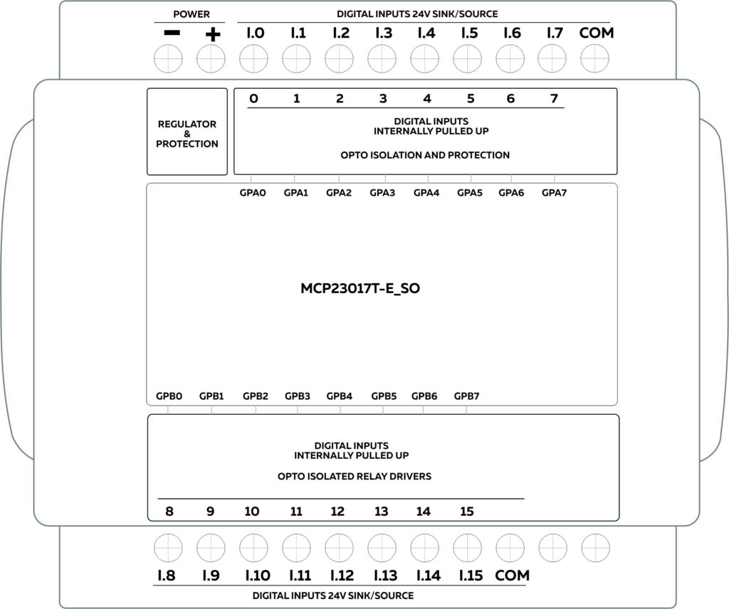
- MCP23017T-E/SO Port Expander
- Address Configurable Over DIP Switch
Expansions Supported
- Digital Input
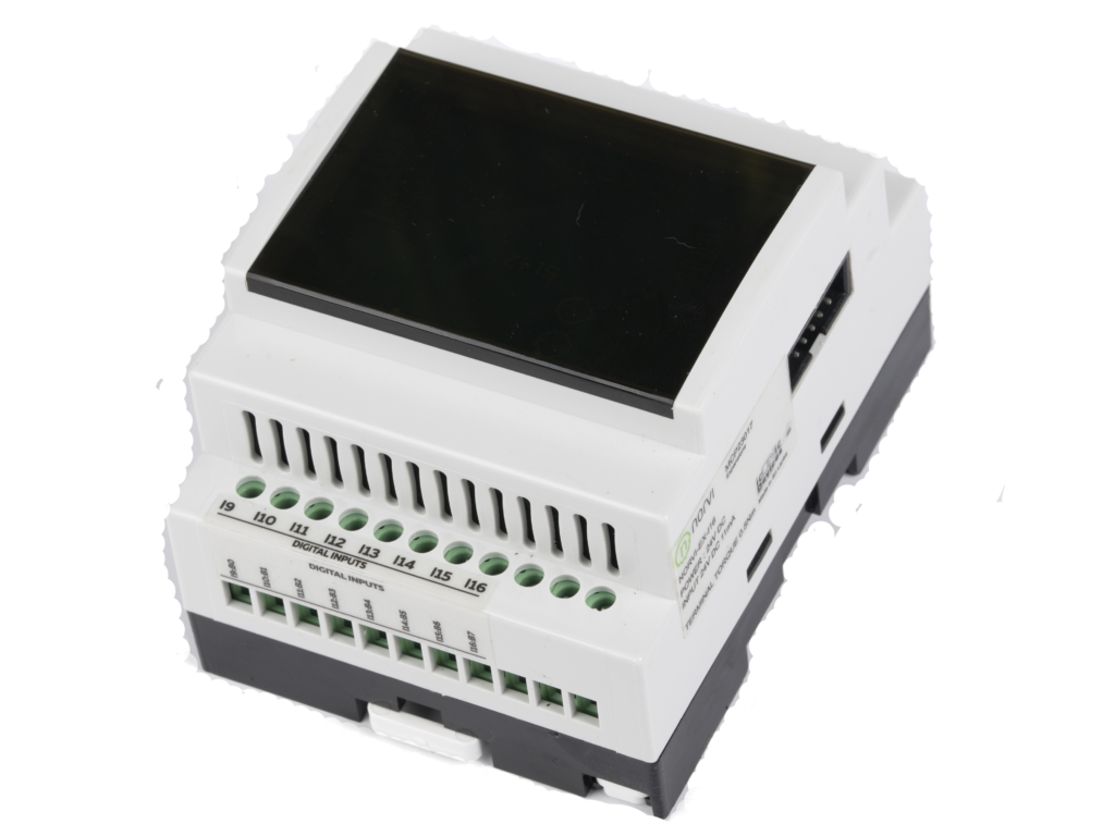
Main #
| Range of Product | NORVI Expansion |
| Product Type | Expansion Module |
| Certifications | EN 61131-2:2007 EN 61010-1:2010+A1:2019 EN IEC 61010-2-201:2018 2014/30/EU- Electromagnetic Compatibility (EMC) Annex III, Part B, Module C |
| Rated supply voltage | 24V DC |
| Communication | I2C |
| Inputs and Outputs | 16 x Digital Inputs |
| Displays and Visual Indicators | 1 LED green |
Complementary #
| Product Unified Code | NORVI EX-I16 |
| Product Part Numbers | NORVI EX-I16 |
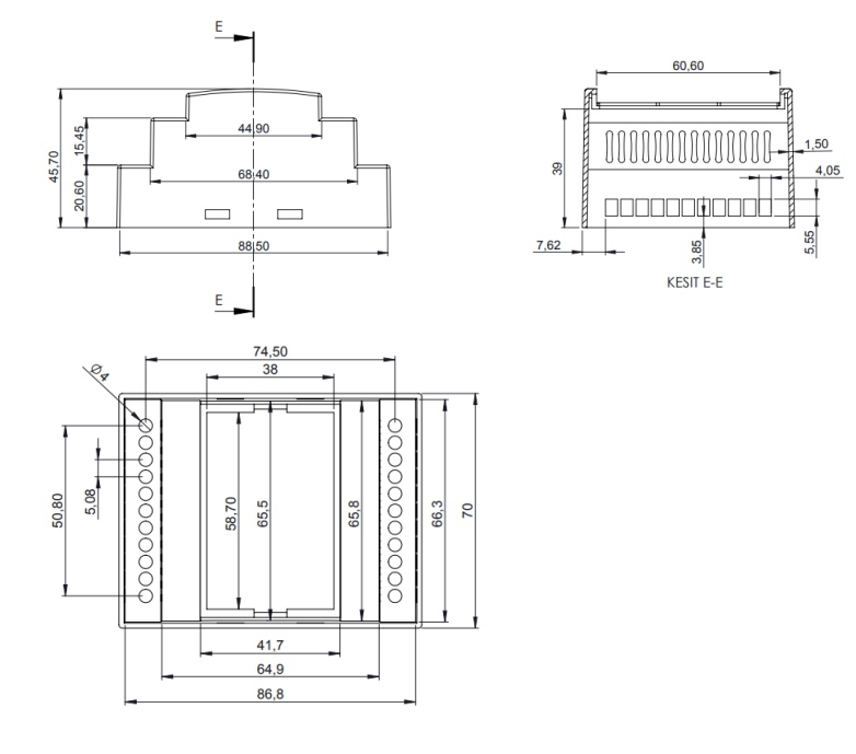
Mechanical Properties #
| Enclosure | NORVI 204 |
| Mounting / Installation Method | DIN RAIL / MOUNTING TABS |
| Terminal Type | Top hat type TH35-15 rail conforming to IEC 60715 Top hat type TH35-7.5 rail conforming to IEC 60715 Plate or panel with fixing kit |
| Terminal Arrangement | Top and Bottom |
| Length | 90.50 mm |
| Height | 56.60 mm |
| Width | 60.60 mm |
Environment #
| IP degree of protection | IP20 |
| Operating altitude | 0 – 2000 meters |
| Operating Temperature | – –10 … +85° C (14…185 °F) |
| Storage altitude | 0 – 3000 meters |
| Shock resistance | 15 gn for 11ms |
| Resistance to electrostatic discharge | 4kV on contact 8kV on air |
| Resistance to electromagnetic fields | 10 V/m (80 MHz …… 1GHz) 3 V/m (1.4 MHz …… 2 GHz) 1 V/m (2 MHz …… 3 GHz) |
Electrical Characteristics
#
Grid Powered Devices #
| Rated Supply Voltage (V) | 24V DC |
| Current Consumption (mA) | 400mA |
| Recommended Power Source | 1A 24V DC |
Processing #
| SOC / MCU | 16-bit-I/O Expander with Serial Interface |
| Module | MCP23017T-E_SO |
| Operating supply voltage | 2.4V to 3.6V |
| I2C SDA | GPIO16 |
| I2C SCL | GPIO17 |
INPUTS and OUTPUTS #
Digital Inputs #
| Number of Digital Inputs | 16 |
| Digital Input Polarity | Sink and Source |
| Digital Input Maximum Voltage | 32V DC |
| Digital Input Minimum Voltage | 18V DC |
| Maximum Switching Frequency | 1 kHZ |
| Terminal Arrangement | Digital Input 0 – GPA0 Digital Input 1 – GPA1 Digital Input 2 – GPA2 Digital Input 3 – GPA3 Digital Input 4 – GPA4 Digital Input 5 – GPA5 Digital Input 6 – GPA6 Digital Input 7 – GPA7 Digital Input 8 – GPB0 Digital Input 9 – GPB1 Digital Input 10 – GPB2 Digital Input 11 – GPB3 Digital Input 12 – GPB4 Digital Input 13 – GPB5 Digital Input 14 – GPB6 Digital Input 15 – GPB7 |
I2C Address Setting #
The I2C address of the expansion module can be configured by switching DIP switches at the bottom of the expansion module. The device can be configured at 8 I2C addresses using the first 3 DIP switches.

Expansion Port #
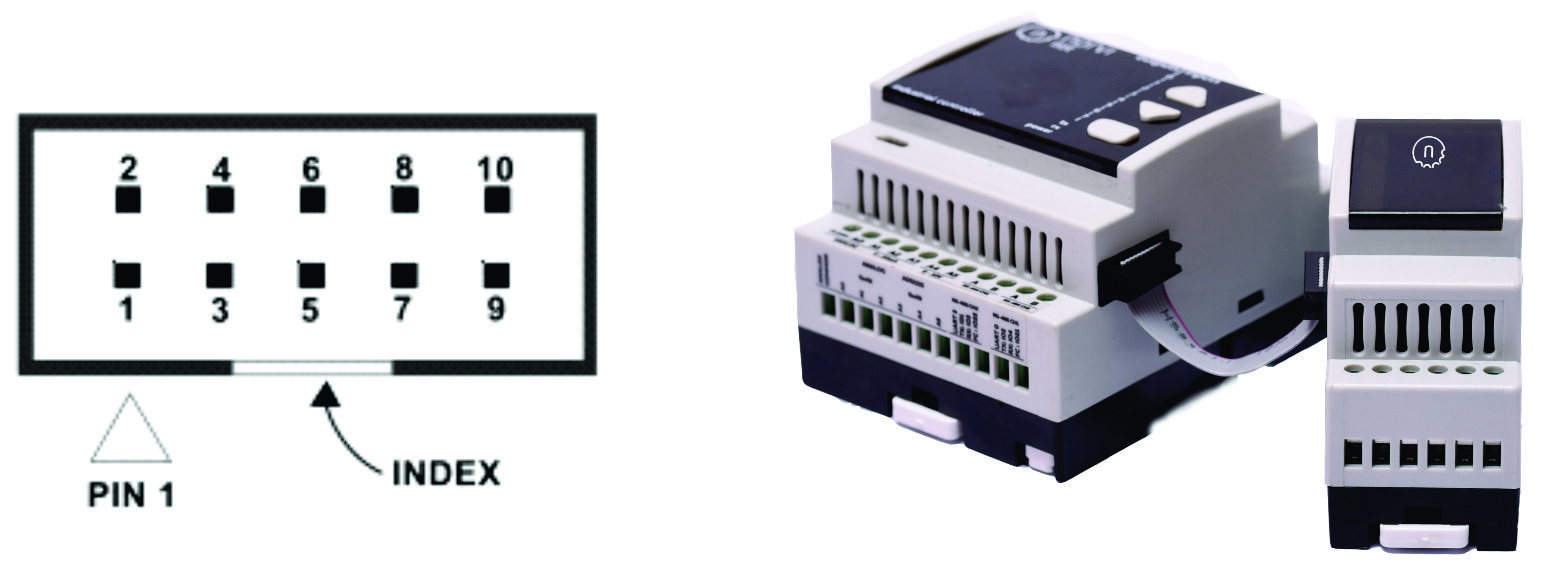
| PIN | ESP32 Connection |
| 1 | TXD0 |
| 2 | GPIO25 |
| 3 | RXD0 |
| 4 | AUX1 |
| 5 | GPIO15 |
| 6 | NRST |
| 7 | SCL2 |
| 8 | AUX2 |
| 9 | SDA2 |
| 10 | GND |


