Posted on

NORVI Controller as a Modbus I/O over RS-485

RS-485 signals are used in a wide range of computer and automation systems. RS-485 is used for low-speed data communications in commercial aircraft cabins’ vehicle bus. It requires minimal wiring, and can share the wiring among several seats, reducing weight.

These are used in programmable logic controllers and on factory floors. Utilizing a series of dedicated interface devices, it allows PCs and industrial controllers to communicate. Since it is differential, it resists electromagnetic interference from motors and welding equipment.

RS-485 is also used in building automation as the simple bus wiring and long cable length is ideal for joining remote devices.

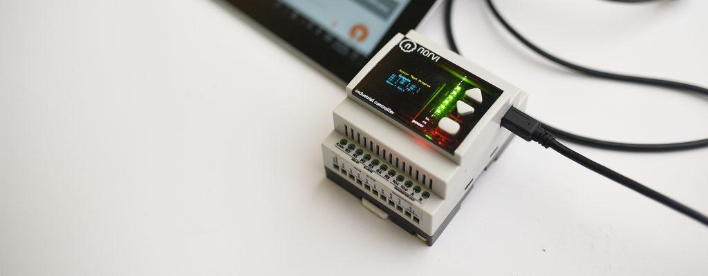
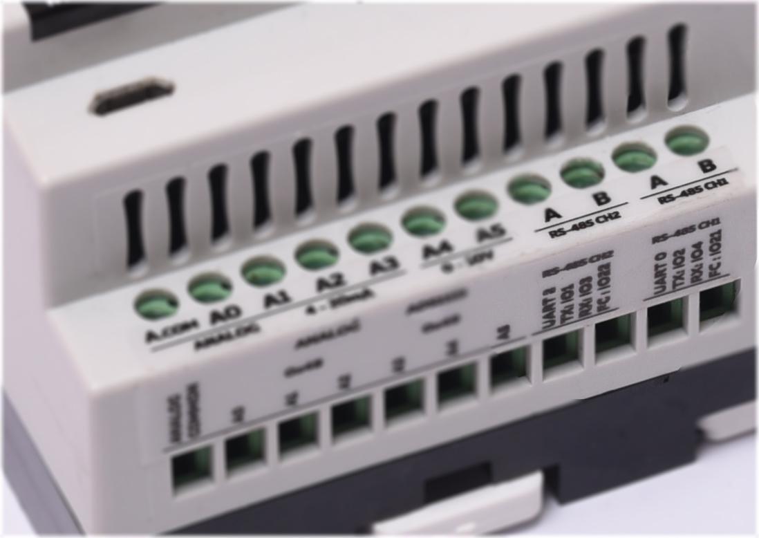
Almost all the NORVI controller has RS-485 connectivity standard or as an option. There are several communication protocols which is supported by RS-485, Modbus RTU and Profibus are the widely used protocols among them.


This article is about compatibility Modbus RTU with RS-485 connection on NORVI Programs.

There are several libraries which we have tested to work with NORVI Controllers.

NORVI IIOT ESP32 / NORVI Agent 1 / NORVI Agent 2
Modbus RTU Master
Library: https://github.com/bertmelis/esp32ModbusRTU
This is the perfect library for MODBUS Master on ESP32 based NORVI IIOT. We can read registers of Modbus slave devices like Energy Meters, and sensors. And we can read values from Programmable Logic Controllers as well.

Modbus RTU Slave
Library: https://github.com/JhonControl/ESP8266-Modbus-RTU-Slave-Emoncms
If you want make NORVI device work as a Modbus slave letting a Modbus master read values from NORVI this library can help you do it.
You can create a Modbus Register in NORVI controller, with just a single line of code. This is useful to make NORVI work with HMI via RS-485.

Modbus TCP Master
Library: https://github.com/bertmelis/esp32ModbusTCP
Library for implementing Modbus TCP connection over WIFI.


NORVI Arita

https://github.com/smarmengol/Modbus-Master-Slave-for-Arduino

https://github.com/yaacov/ArduinoModbusSlave

Posted on

NORVI expands its Industrial IoT Device range

Industrial IoT Devices


NORVI expands its Industrial IoT Device range 

Out of hundreds of devices out there on the market we wish to serve a different aspect of Industrial IoT Devices , 
Flexibility in expansion, communication and reliability is our main focus. Making a reliable device, reliable on industrial environment is challenging while maintaining flexibility.
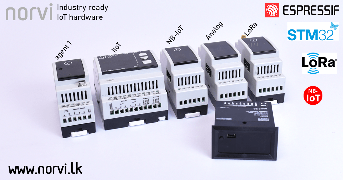
We were doing Research on introducing a series of expansion modules for our key IoT Hardware, NORVI IIOT and NORVI Arita.
Finally, we were able to release 7 expansion modules as,
1) NB-IOT with BC95-G
2) LoRa with Reyax
3) Analog (0-10V)
4) Analog (4-20mA)
5) Temperature (thermocouple)
6) Temperature (RTD)
7) Load cell


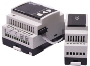
All the modules communicate with the controller via expansion port on the side of the controller. Expansion ports are facilitated with I2C and UART lines., There is no hassle in programming for the expansion modules, they connect with the host controller as usual modules. 
For more information on expansion modules
https://norvi.lk/norvi-expansion/

Additional to its expansion modules, we launched two new products for more simpler applications.
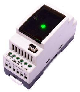
NORVI Agent 1 is a model with lesser input count than NORVI IIOT with options to choose the type of micro-controller depending on application. It is offered with either ESP32-WROVER32 or STM32L series ultra low power micro-controller. As communication options NB-IoT and LoRA comes built in. It has RGB led on the top of the controller and can be programmed as a status indicator.
If you with to go battery powered without WIFI connectivity STM32L series micro-controller can provide years of battery life. 
https://norvi.lk/industrial-iot-node/

Industrial IoT Node
Agent 1 IoT Device with pixel led


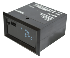
NORVI Agent 2 is designed for panel mount applications with ESP32-WROOM32. It has a 0.96 OLED Display for use with monitoring and diagnosing applications. As usual, it is USB programmable with 24V tolerant digital inputs.
https://norvi.lk/industrial-iot-node-2/


You can check the new product range at
https://norvi.lk/products/

Posted on

Industrial Arduino Norvi Getting started guide

Industrial Arduino NORVi

Getting started with Industrial Arduino

It really does not need to be documented on getting started with NORVI. Still we have made a guide to clear your doubts.
NORVI products represents a development board with industrial level protection
and attenuation enclosed in an industrial enclosure.
The device comes marked with all necessary information to start your projects.

Let’s start with
Power supply.

NORVI Industrial Arduino is rated: 24V DC 1A
24V DC 1A Power supply is recommended.
All the NORVI Industrial Arduino can be powered up with the USB Connection, It is required to use an external power supply to get the full functionality
.
`

Programming the controller.

All the devices are standard with a USB Port for programming.
NORVI Models will be recognized as following within the IDE
Table1.0 

NORVI CEMA

Arduino
micro

NORVI IIOT

COM port

NORVI ARITA MEGA2560

ARDUINO
MEGA2560

NORVI ARITA STM32F103VCT6

ARDUINO Maple


Supported IDE

NORVI ARITA
NORVI CEMA


NORVI IIOT
   

Selecting the board
Select the appropriate Arduino board according to NORVI
model. Refer
Table1.0

Addressing Inputs & Outputs
It is done the same way you address, a development boards pin with your programming IDE.
Below are few examples for better understanding

NORVI IIOT : Relay ON/OFF


Let’s say we need to turn on R0 Relay.


Referring to Quick Start Guide or terminal marks
R0 is connected to IO 14 , Arduino code example is as
follows


void setup() {

// Declare IO14 as OUTPUT

pinMode(14, OUTPUT);

}

void loop() {

// put your main code here, to run
repeatedly:

digitalWrite(14, HIGH); // Turn ON 14(R0)

delay(1000);

digitalWrite(14, LOW); // Turn
OFF 14(R0)

delay(1000);

}

NORVI IIOT : Digital Input


Reading status of I0 and printing it on Serial.
Referring to Quick Start Guide or terminal marks
I0 is connected to IO 18, Arduino code example is as
follows

void setup() {

// Declare IO14 as OUTPUT

Serial.begin(9600);

pinMode(18, INPUT);

}

void loop() {

// put your main code here, to run
repeatedly:

Serial.println(digitalRead(18));

delay(1000);

}

You can download quick start
guides and reference manuals via following link
https://norvi.lk/support/

Order Online
https://norvi.lk/products/