Posted on

NORVI RPI HMI – Reliable Raspberry Pi-based HMI for Industrial Automation

Raspberry Pi-based HMI

The NORVI RPI Industrial Controller offers a versatile, Raspberry Pi-based Human-Machine Interface (HMI) tailored for industrial automation engineers. Combining the flexibility of Raspberry Pi with the ruggedness required for industrial environments, the NORVI RPI HMI delivers a powerful control system that’s easy to deploy and scale.

Key Features of NORVI RPI HMI

  • Raspberry Pi Integration:

   By incorporating Raspberry Pi CM4 into an industrial-grade HMI, the NORVI RPI HMI gives engineers a cost-effective, high-performance control system that supports both data acquisition and real-time process control.

  • All-in-One Industrial Controller:

   The NORVI RPI HMI combines control, data collection, and connectivity into a single device, streamlining industrial processes for engineers. It features digital and analog inputs for full control over sensors and actuators.

  • Seamless Integration:

   With industrial communication protocols built-in, the NORVI RPI HMI integrates effortlessly into existing systems, allowing engineers to enhance their automation setups without compatibility issues.

Solving Key Automation Challenges

  • Limited Inputs/Outputs:

   The NORVI RPI HMI provides engineers with the expanded I/O capabilities necessary for complex automation tasks, unlike many Raspberry Pi-based controllers with limited inputs and outputs.

  • Durability in Harsh Environments:

   Built for industrial settings, this HMI handles the power and environmental demands that engineers often face when deploying Raspberry Pi in critical operations.

Posted on

NORVI ESP32-S3 HMI – Advanced Human-Machine Interface for Industrial Applications

Advanced Human-Machine Interface

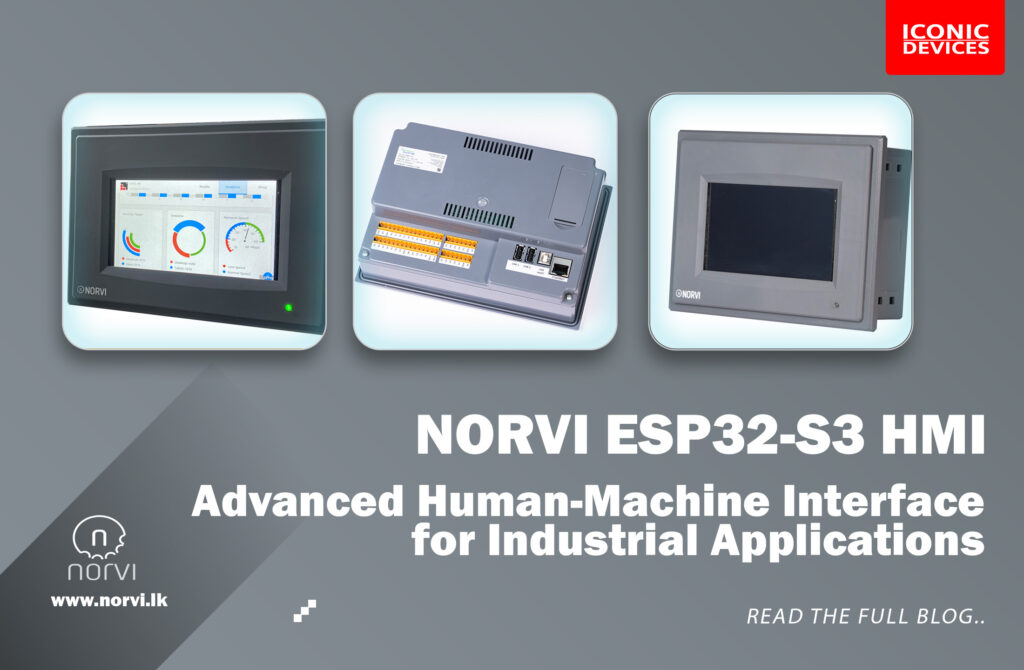
In Industrial Automation, Advanced Human-Machine Interface (HMI) play a crucial role in facilitating control and monitoring of processes. 

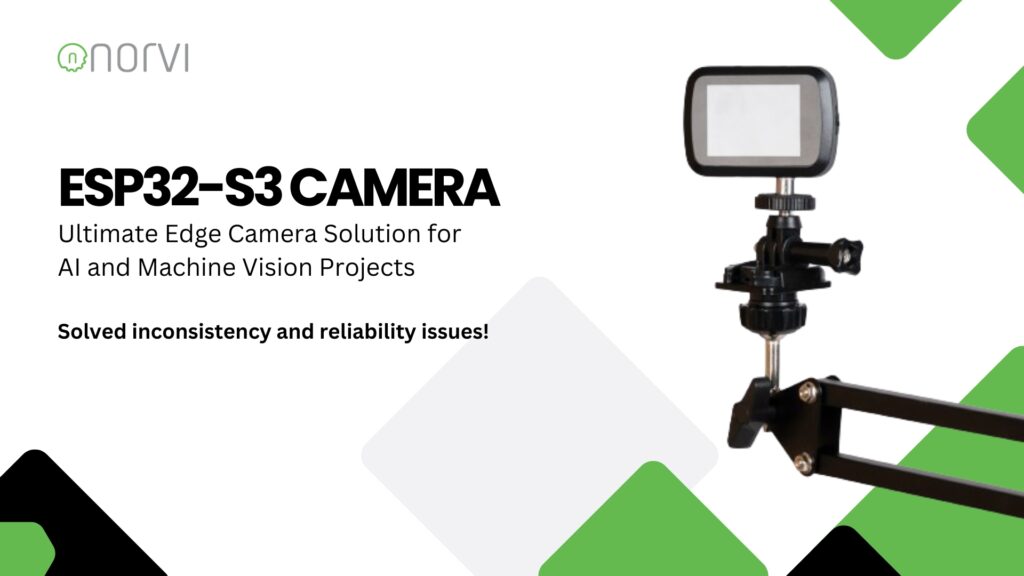
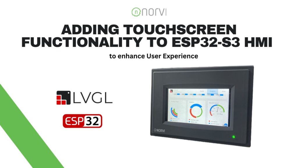
The NORVI ESP32-S3 HMI is designed to provide a robust, AI-capable interface solution that meets the needs of modern automation systems. Built on the ESP32-S3 platform, this HMI offers unparalleled performance, real-time interaction, and flexibility for various industrial applications.

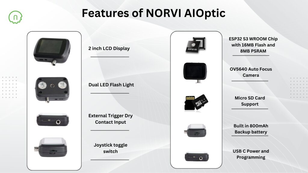
Key Features of NORVI ESP32-S3 HMI

Advanced Human-Machine Interface
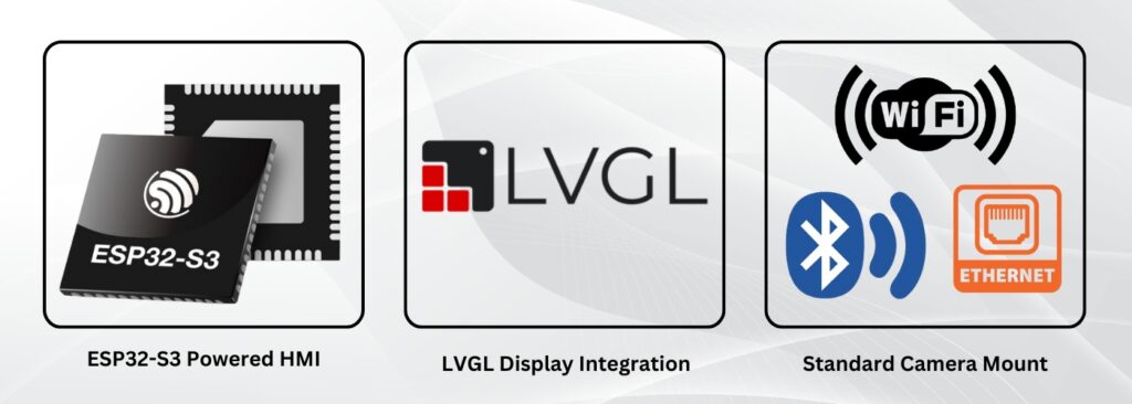
  • ESP32-S3 Powered HMI:

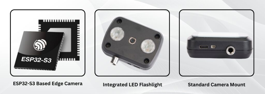
   Featuring the powerful ESP32-S3 microcontroller with 8MB PSRAM, the NORVI ESP32-S3 HMI offers engineers high performance for edge computing, enabling advanced control systems with minimal latency.

  • LVGL Display Integration:

   The NORVI ESP32-S3 HMI supports LVGL, an advanced graphics library, ensuring that engineers can build visually intuitive interfaces. This is ideal for creating dynamic control panels and real-time data visualization.

  • Comprehensive Connectivity:

   Equipped with Wi-Fi and Bluetooth with Ethernet, the NORVI ESP32-S3 HMI allows for seamless integration into existing industrial networks, offering remote control and monitoring capabilities.

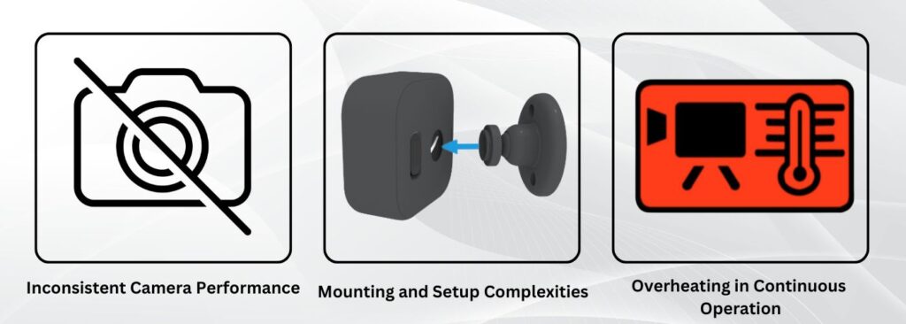
Addressing Industry Challenges

Advanced Human-Machine Interface
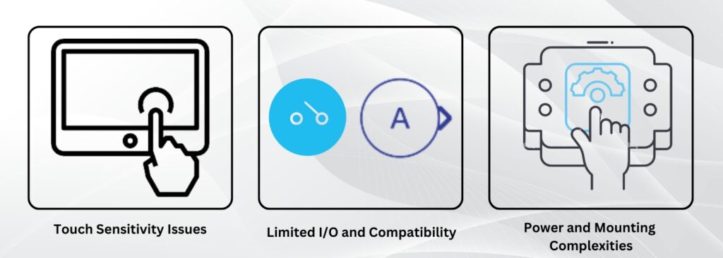
  • Touch Sensitivity Issues:

   Unlike many HMIs that suffer from unreliable touch performance, the NORVI ESP32-S3 HMI delivers accurate, responsive touch input, ensuring smooth interaction in even the harshest industrial environments.

  • Limited I/O and Compatibility:

   The NORVI ESP32-S3 HMI overcomes compatibility challenges faced by other products by offering versatile I/O options and ensuring seamless integration with industrial equipment.

  • Power and Mounting Complexities:

Designed for industrial use, this HMI features a simplified mounting system and is optimized for continuous operation without overheating or power inconsistencies.

The NORVI ESP32-S3 HMI stands out as a cutting-edge solution for industrial automation, delivering powerful performance, real-time interaction, and flexibility. With its ESP32-S3 microcontroller, LVGL display integration, and extensive connectivity options, this HMI ensures efficient control and monitoring across various applications. 

Its robust design and responsive touch interface make it ideal for challenging industrial environments, solving common issues such as touch sensitivity and power management. For engineers looking for an advanced, AI-capable HMI, the NORVI Advanced Human-Machine Interface is an optimal choice.

If you need to know more details about NORVI Advanced Human-Machine Interface;

Visit the product Page: https://norvi.lk/esp32-based-hmi-norvi-industrial-arduino-with-lvgl-support/

Contact Us: https://norvi.lk/contact-us/

Posted on

NORVI AIOptic – Elevating Edge Camera Solutions for Industrial Applications

In the realm of industrial automation and IoT, reliable and powerful edge devices are paramount. The NORVI AIOptic-Edge Camera Solutions, based on the ESP32-S3, offers a robust solution for industries that require efficient and high-performing image capture and processing. Specifically designed for engineers and integrators in automation, this edge camera provides a seamless way to implement AI-powered vision systems on the edge

Key Features of NORVI AIOptic-Edge Camera Solutions

  • ESP32-S3 Based Edge Camera:

The NORVI AIOptic is powered by the ESP32-S3, a microcontroller designed to handle AI-based tasks on the edge. The ESP32-S3 has dual-core Xtensa LX7 processors (240 MHz), 512 KB SRAM, 384 KB ROM, up to 16 MB flash, and 8 MB PSRAM support, integrated with OV5640 5MP(megapixels) camera. This allows for real-time image recognition and processing, eliminating the need for cloud-based processing, which can introduce latency and data privacy concerns.

  • Integrated LED Flashlight:

For environments with inconsistent lighting, the built-in LED flashlight ensures that the camera captures clear images in low-light conditions, making it ideal for industrial monitoring applications.

  • Standard Camera Mount for Easy Installation:

   Designed with industrial environments in mind, the NORVI AIOptic features a standard camera mount, allowing engineers to easily install the device in fixed or moving positions without the need for custom fixtures.

Solving Industry-Specific Challenges

The NORVI AIOptic addresses several common challenges faced by engineers working with industrial camera systems:

  • Inconsistent Camera Performance:

In industrial settings, many camera modules fail to deliver consistent image quality, particularly in harsh environments. The NORVI AIOptic overcomes this by providing stable, high-quality image processing tailored for industrial use.

  • Mounting and Setup Complexities:

   Traditional camera modules often lack proper mounting systems, leading to installation delays. With its standard camera mount, the NORVI AIOptic simplifies installation, allowing for easy setup in both static and dynamic environments.

  • Overheating in Continuous Operation:

   Many edge cameras struggle with overheating during prolonged usage, especially in industrial conditions. The NORVI AIOptic is engineered to handle extended periods of operation, making it reliable for long-term projects.

Tailored for Industrial Engineers

With features like real-time edge processing, robust performance in low-light conditions, and simple installation, the NORVI AIOptic is designed specifically for industrial automation engineers seeking a reliable, AI-enabled camera solution. 

Whether you’re developing an image recognition system or monitoring operations in real-time, Norvi’s edge technology delivers the performance and flexibility required for modern industrial environments.

Visit the product Page to know more about Edge Camera Solutions: https://norvi.lk/product/esp32-cam/

Contact Us: https://norvi.lk/contact-us/

Posted on

ESP32 Advanced Camera for AI and Machine Vision Projects

When working on AI and machine vision projects, consistency and reliability are key. However, many ESP32-based camera modules available on the market today fall short, suffering from issues like overheating, inconsistent lighting, and lack of flexibility in mounting. Try the NORVI AIOptic, ESP32 Advanced Camera, an edge camera designed to address these challenges head-on, offering a comprehensive solution for your imaging needs. 

Overcoming Common Challenges in ESP32-Based Camera Projects

Many developers face frustrations with the inconsistency and unreliability of existing ESP32-based cameras. From poor-quality camera modules to overheating problems, these issues can significantly hamper project development. Additionally, the lack of built-in displays and battery backup often makes standalone operation difficult, especially in remote or demanding environments.

NORVI AIOptic addresses these concerns with precision

  1. High-Quality Camera Module: Equipped with the OV5640 auto-focus camera, NORVI AIOptic ensures clear and sharp images every time. Unlike fixed-focus alternatives, this module adapts to various scenarios, providing the flexibility that other cameras lack.
  2. Dual LED Flashlights: Image recognition projects require consistent lighting, which is why NORVI AIOptic comes with two powerful LED flashlights. These LEDs can be adjusted to suit different lighting conditions, ensuring that your images are clear and well-lit, regardless of the environment.
  3. Built-In 2-Inch Display: One of the major drawbacks of other ESP32 camera modules is the absence of a built-in display, making on-the-spot monitoring impossible. NORVI AIOptic solves this with a 2-inch TFT LCD, allowing for real-time viewing and adjustments.
  4. Battery Backup and Overheating Solutions: NORVI AIOptic includes an 800mAh backup battery, ensuring uninterrupted operation even during power outages. Additionally, it’s designed with a heat sink to mitigate overheating, guaranteeing reliable, continuous use.

Why NORVI AIOptic Stands Out

The NORVI AIOptic isn’t just another ESP32-based camera. It’s a carefully engineered solution that combines powerful features with practical design:

  • ESP32 S3 WROOM Chip: With 16MB Flash and 8MB PSRAM, this chip ensures fast processing and ample storage for your projects.
  • Standard Camera Mount: NORVI AIOptic supports standard camera mounts, offering ease of installation and flexibility in various environments.
  • MicroSD Card Support: Store large amounts of data with the built-in microSD card slot, making data management and retrieval straightforward.
  • External Trigger and USB-C Power: Easily integrate the camera into your systems with external triggers and enjoy the convenience of USB-C power and programming.

Applications of NORVI AIOptic

Thanks to its robust design and versatile features, NORVI AIOptic is ideal for a wide range of applications:

  • Species and Habitat Monitoring: The NORVI AIOptic’s auto-focus camera and dual LED flashlights allow you to monitor wildlife with precision.
  • Plant Monitoring: Keep track of plant growth and health with consistent imaging, no matter the lighting conditions.
  • Image Recognition and AI Projects: From facial recognition to object detection, NORVI AIOptic is the perfect tool for integrating AI and machine learning into your projects.
  • Barcode Reading: Easily implement barcode scanning solutions with the high-quality camera and reliable processing power of the ESP32 S3 chip.
  • People Counting: Use NORVI AIOptic in retail environments or public spaces for accurate people counting and data collection.
  • Package Delivery Detection: Enhance logistics operations by using the NORVI AIOptic to detect and verify package deliveries in real-time. 

If you’re tired of the limitations and inconsistencies of other ESP32-based camera modules, it’s time to upgrade to the NORVI AIOptic, ESP32 Advanced Camera. Designed with the needs of modern developers in mind, this edge camera delivers reliability, flexibility, and high-quality performance, making it the ultimate choice for your next AI, machine vision, or image recognition project.

Visit our product page : https://norvi.lk/product/esp32-cam/

Or, Contact us at [email protected]

Posted on

Remote Environmental Monitoring with NORVI M12-C Series

M11 E Series

The NORVI M12-C Series battery-powered IoT node is an ideal solution for remote environmental monitoring in locations without grid power. Designed for standalone installations, it leverages the STM32L1 microcontroller. It supports various low-power communication options such as GSM/LTE, NB-IoT, LoRa, and Zigbee 3.0, ensuring efficient data transmission while maximizing battery life.

Scenario

In a remote forest area, an environmental research team must monitor various environmental parameters such as temperature, humidity, and soil moisture. The absence of grid power poses a significant challenge.

Solution

Deployment: The NORVI M12-C Series devices are deployed at multiple monitoring points across the forest.

Power Supply: Each device is powered by four inbuilt AA batteries, which also provide up to 12V output to power external sensors.

Sensors: Various environmental sensors are connected to the devices, using flexible I/O combinations to measure temperature, humidity, and soil moisture levels.

Data Transmission: Using the supported low-power communication options (e.g., LoRa for long-range communication), the devices transmit collected data to a central server for analysis. The communication method is chosen based on the specific needs and range requirements of the deployment area.

Durability: The IP67-rated enclosure ensures that the devices can withstand harsh outdoor conditions, including rain, dust, and extreme temperatures.

Benefits

Energy Efficiency: Low-power communication options and efficient power management extend battery life, reducing the need for frequent maintenance.

Reliable Data Collection: Continuous and reliable data collection from remote locations aids in comprehensive environmental monitoring and research.

Scalability: The solution can be easily scaled by adding more devices to cover larger areas or monitor additional parameters.

Cost-Effective: Eliminates the need for extensive infrastructure setup and grid power, making it a cost-effective solution for remote monitoring applications.

This application showcases the versatility and robustness of the NORVI M12-C Series in addressing the challenges of remote environmental monitoring, providing a reliable and efficient solution for data collection in off-grid locations.

Visit the product page: https://norvi.lk/product/ec-m12-cg-cx/

Or, Contact us at [email protected]

Posted on

Industrial Grid-Powered Monitoring with NORVI SSN M11-E Series

With the advancement of Industry 4.0, the demand for robust, real-time monitoring systems in industrial environments has surged. The NORVI SSN M11-E series, using the ESP32-WROOM32 System on Chip (SoC), presents a potent solution for such applications. This series offers flexible Input/Output (I/O) configurations, a wide input voltage range, and robust communication capabilities, making it ideal for a broad spectrum of industrial monitoring tasks such as Industrial Grid-Powered Monitoring.

Key Features

M11 E Series

Versatile I/O Configurations

The M11-E series comprises several models, each tailored to specific sensor inputs and communication requirements:

  • EC-M11-EG-C1: 2 Digital Inputs, 2 Analog Inputs (0 – 10V DC), 1 RS-485 Communication
  • EC-M11-EG-C2: 2 Digital Inputs, 1 RS-485 Communication
  • EC-M11-EG-C3: 1 Load Cell Input
  • EC-M11-EG-C4: 1 Thermocouple Input
  • EC-M11-EG-C5: 1 I2C Communication, 1 3.3V/5V DC Output

Robust Communication

The series supports expansions for GSM/LTE, NB-IoT, and LoRa, ensuring reliable data transmission in diverse environments. Additionally, the RS-485 communication port enables stable, long-distance data transfer within industrial settings.

Wide Input Voltage Range

Operating within a 9 – 36V DC range, the M11-E series can be seamlessly integrated into existing industrial power infrastructures, offering flexibility and ease of deployment.

Industrial Design

Encased in an IP67-rated enclosure, the M11-E series is engineered to withstand harsh industrial conditions, including exposure to dust and water. This ensures durability and reliability in demanding environments.

Application Implementation

Initialization

The initial phase of deploying an industrial monitoring application with the M11-E series involves the setup of GPIO (General-Purpose Input/Output), ADC (Analog-to-Digital Converter), and communication interfaces such as RS-485. 

Proper initialization ensures accurate data acquisition and reliable communication.

Sensor Data Acquisition

The device periodically samples data from connected sensors. 

Digital inputs monitor binary states (e.g., on/off conditions), while analog inputs measure varying signals, providing detailed information about environmental parameters. 

Specific models also support data acquisition from load cells, thermocouples, or I2C sensors, tailored to the application requirements.

Data Processing

Once collected, the data undergoes processing and formatting for transmission. 

This step includes filtering noise, scaling sensor readings, and converting raw data into actionable metrics. 

Proper data processing ensures that the transmitted data is precise and useful for subsequent analysis.

Data Logging

To enhance system reliability, M11-E series devices can log data locally. 

This is crucial for scenarios where communication with the remote server is intermittent. 

Local data storage ensures no data loss and facilitates data transmission once communication is restored.

Communication

The processed data is transmitted to a remote server using the chosen communication protocol. 

RS-485 offers a stable wired connection for long-distance data transfer, while GSM/LTE and LoRa provide wireless options suitable for different industrial environments. 

Ensuring robust communication is essential for real-time monitoring and timely decision-making.

Error Handling

Effective error handling is vital in industrial applications. 

The system must detect and manage communication failures, power issues, and sensor malfunctions. 

Implementing retry mechanisms, fallbacks, and alerts ensures the system remains operational and reliable.

Power Management

M11-E series devices are designed to operate efficiently within a wide input voltage range. 

Monitoring the power supply and managing power consumption is critical to prevent downtime and ensure continuous operation in industrial settings.

Conclusion

The NORVI SSN M11-E series offers a comprehensive solution for industrial grid-powered monitoring applications. Its versatile I/O configurations, robust communication capabilities, and industrial design make it suitable for various industrial environments. Leveraging the ESP32-WROOM32 SoC, these devices provide flexibility, performance, and reliability, essential for modern industrial monitoring needs. Whether monitoring sensor values or parameters from external devices, the M11-E series stands out as a dependable choice for industrial IoT applications.

ESP32 PLC


Visit NORVI M11-E Series Page Now; Here

Or, Contact our Technical support team for all of your technical problems at [email protected]

Posted on

Raspberry Pi HMI Node-RED Introduction: Controlling Digital Inputs

Example of  Raspberry Pi HMI Node-RED. NORVI has a set of node-red nodes that makes programming easy. 

Here is an example of using the Raspberry PI HMI Digital Input node for Node-RED. This node facilitates the control of NORVI-RPI-HMI inputs.

The Raspberry HMI supports Node-Red programs. 

HMI-I1 Node :

The HMI-I1 node serves as a digital input node, representing the inputs of the HMI. It generates a “msg. payload” with either a 0 or 1 depending on the state of the input pin. Configuration of this node involves selecting the desired input.

Inputs: msg. payload (Boolean) – The payload will be a TRUE or a FALSE.

Outputs: msg. payload (Boolean) – The payload will be a TRUE or a FALSE.

TRIGGER TYPE: RISING, FALLING, BOTH

INPUT = SELECT INPUT NUMBER

Lorem ipsum dolor sit amet, consectetur adipiscing elit. Ut elit tellus, luctus nec ullamcorper mattis, pulvinar dapibus leo.

Example Program: Raspberry Pi HMI Node-RED - Controlling Digital Inputs

Let’s create a simple example program using the RPI-HMI-IN node. When a button is pressed it contains true and false and this represents a trigger. Here, to display the program in the Node-RED dashboard added a switch node (digi 01 & digi 02) to it as a dashboard node.

After setting the configuration of the program, the user interface of the RPI HMI should be as below.

  • Digital Input 1 ON and Digital Input 2 OFF 
  • Digital Input 1 OFF and Digital Input 2 ON

This schematic shows the connection between the RPI-HMI inputs. When the inputs are in the OFF state, the GPIO goes LOW, and when the input is in the ON state, the GPIO goes HIGH.

Posted on

Node-Red on RPI HMI Introduction: Controlling Transistor Outputs

Example of Node-Red on RPI HMI applications. NORVI has a set of node-red nodes that makes programming easy.


Here is an example of using the Raspberry PI HMI Transistor Outputs ON and OFF node for Node-RED. This node facilitates the control of NORVI-RPI-HMI outputs. Check out How Node-Red on RPI HMI works.

The Raspberry HMI supports Node-Red programs.I

HMI-Q1 Node

The HMI-Q1 node serves as a digital output node. It accepts a “msg. payload” with either a 0 or 1, setting the selected physical pin high or low based on the passed value. 

Inputs: payload number | string | Boolean
When sending a message to the Node-RED HMI-Q1 node, use any of these inputs to control the output. For example, sending Boolean true turns the output on, and sending Boolean false turns it off. Similarly, sending either the number 1 or the string “ON” can turn the output on, depending on how the flow is configured.

Output = Desired output can be selected in node configuration.

Example of Node-Red on RPI HMI

Let’s create a simple example program using the RPI-HMI-OUT node. When a button is pressed, it contains true and false values, representing a trigger. Display the program on the Node-RED dashboard by adding a switch node (Q7 ON & Q7 OFF) as a dashboard node.

To display the program in the Node-RED dashboard add a button node (Toggle Switch7) to it as a dashboard node.

After setting the configuration of the program, the user interface of the RPI HMI should be as below.

  • ON state – When the output is in the ON state, it means the output is activated, and the LED associated with it is illuminated.
  • OFF state – When the output is in the OFF state, it means the output is deactivated, and the LED associated with it is turned off.

This schematic shows the connection between the RPI-HMI output and the LED. The RPI-HMI output is connected to the GND end of the LED, while the other end of the LED is connected to a resistor, and then to the power in(24+).

Posted on

Adding Touchscreen Functionality to ESP32-S3 HMI

Adding Touchscreen Functionality to ESP32-S3 HMI

ESP32 NORVI HMI is a powerful HMI resistive touch screen with an 800*480 resolution LCD display. It uses the ESP32-S3-WROOM-1-N4R8 module as the main control processor, with a dual-core 32-bit microprocessor, integrated WiFi and Bluetooth wireless functions, a main frequency of up to 240MHz, providing powerful performance and versatile applications, suitable for IoT application devices and other scenes. Let’s see how advanced Touchscreen Functionality works with ESP32 HMI.

The module includes a 5.0-inch LCD display and a driver board. The display screen uses resistive touch technology. It supports a development environment such as Arduino IDE and is compatible with the LVGL graphics library. This enables developers to customize their UI interfaces and create interesting projects quickly and easily, greatly shortening the development cycle.

A 5-inch resistive touch display is a touchscreen technology with a layered structure, comprising a flexible top layer and a rigid bottom layer separated by insulating dots. When pressure is applied, these layers make contact at specific points, and touch input is detected by measuring changes in voltage. Some common features of the touch panel are,

  • Accuracy and Pressure Sensitivity: Resistive touchscreens provide accurate touch input by detecting the precise point of contact.
  • Cost-Effectiveness: Resistive touch panels are cost-effective to produce, making them a popular choice for budget-friendly displays.
  • Versatility and Compatibility: Compatible with various input methods, resistive touchscreens can be operated with any object that applies pressure.
  • Calibration Requirements: Periodic calibration may be necessary to maintain accurate touch response.

To add the Touchscreen Functionality to an ESP32-S3 HMI, it will need to use a combination of the ESP32-S3 microcontroller, a suitable Touch library, and the LVGL  graphics library. Below are the general steps to add these functionalities:

  1. Set Up Development Environment:

Install Arduino IDE on PC.

Integrate ESP32 board support in Arduino IDE.

Install required libraries for ESP32, touch, and LVGL. 

The Touch library may need to use a library that is compatible with the specific 5-inch resistive touch.

  1. Include Libraries in Arduino Sketch:

Include the required libraries at the beginning of the Arduino sketch:

#include <XPT2046_Touchscreen.h>

#include <lvgl.h>


  1. Initialize Touch parameters:
  • Initialize the set points

The touch screen set points are configured through an example code provided by a touch library. By executing the code and interacting with the four sides of the display, the corresponding values are displayed in the serial monitor. This process enables the determination of touchscreen set points based on the user’s input and observation of the serial output.

#define TOUCH_MAP_X1 270

 #define TOUCH_MAP_X2 3800

 #define TOUCH_MAP_Y1 3600

 #define TOUCH_MAP_Y2 330

  • Variables touch_last_x and touch_last_y store the last touched coordinates.

int touch_last_x = 0, touch_last_y = 0;

#if defined(TOUCH_XPT2046)

XPT2046_Touchscreen ts(TOUCH_XPT2046_CS, TOUCH_XPT2046_INT);

  • Touch Initialization Function.

void touch_init() {

#if defined(TOUCH_XPT2046)

  SPI.begin(TOUCH_XPT2046_SCK, TOUCH_XPT2046_MISO, TOUCH_XPT2046_MOSI, TOUCH_XPT2046_CS);

  ts.begin();

  ts.setRotation(TOUCH_XPT2046_ROTATION);

  • Check for Touch Signal.

bool touch_has_signal() {

#if defined(TOUCH_XPT2046)

  return ts.tirqTouched();

  • Check if Touched

bool touch_touched() {

#if defined(TOUCH_XPT2046)

  if (ts.touched())  {

    TS_Point p = ts.getPoint();

  • Check if Touch Released.

bool touch_released(){

if defined(TOUCH_XPT2046)

  return true;


Example

This touch code provides an abstraction layer for the touch library, allowing the user to easily understand. The code includes initialization, event handling, and functions to check if the screen is touched or released. 

If buttonXMin, buttonXMax, buttonYMin, and buttonYMax represent the borders or boundaries of the region on the touch screen corresponding to the position of the button. let’s see how to configure a button, and set its action. 

#include <XPT2046_Touchscreen.h>

#define TOUCH_CS 10 // Example pin for touch CS

XPT2046_Touchscreen ts(TOUCH_CS);

#define BUTTON_PIN 7 // Example pin for the button

void setup() {

  Serial.begin(9600);

  ts.begin();

  pinMode(BUTTON_PIN, INPUT);

}

void loop() {

  // Read touch input

  TS_Point p = ts.getPoint();

  // Check if the touch screen is touched

  if (p.z > MINPRESSURE && p.z < MAXPRESSURE) {

    // Process touch input (e.g., map coordinates, perform actions)

    int mappedX = map(p.x, TS_MINX, TS_MAXX, 0, 800); // Adjust based on display size

    int mappedY = map(p.y, TS_MINY, TS_MAXY, 0, 480); // Adjust based on display size

    Serial.print(“Touched at X: “);

    Serial.print(mappedX);

    Serial.print(“, Y: “);

    Serial.println(mappedY);

    // Check if the touch is in the region of the button

    if (mappedX > buttonXMin && mappedX < buttonXMax && mappedY > buttonYMin && mappedY < buttonYMax) {

      // Button is pressed, perform action

      Serial.println(“Button Pressed!”);

      // Add button action here

    }

  }

}

Hope you get the way of adding Touchscreen Functionality to ESP32-S3 HMI

Check-out the ESP32-S3 HMI or, contact us at s[email protected]