1. Introduction to the RPI-PC-AX8-TO7 #
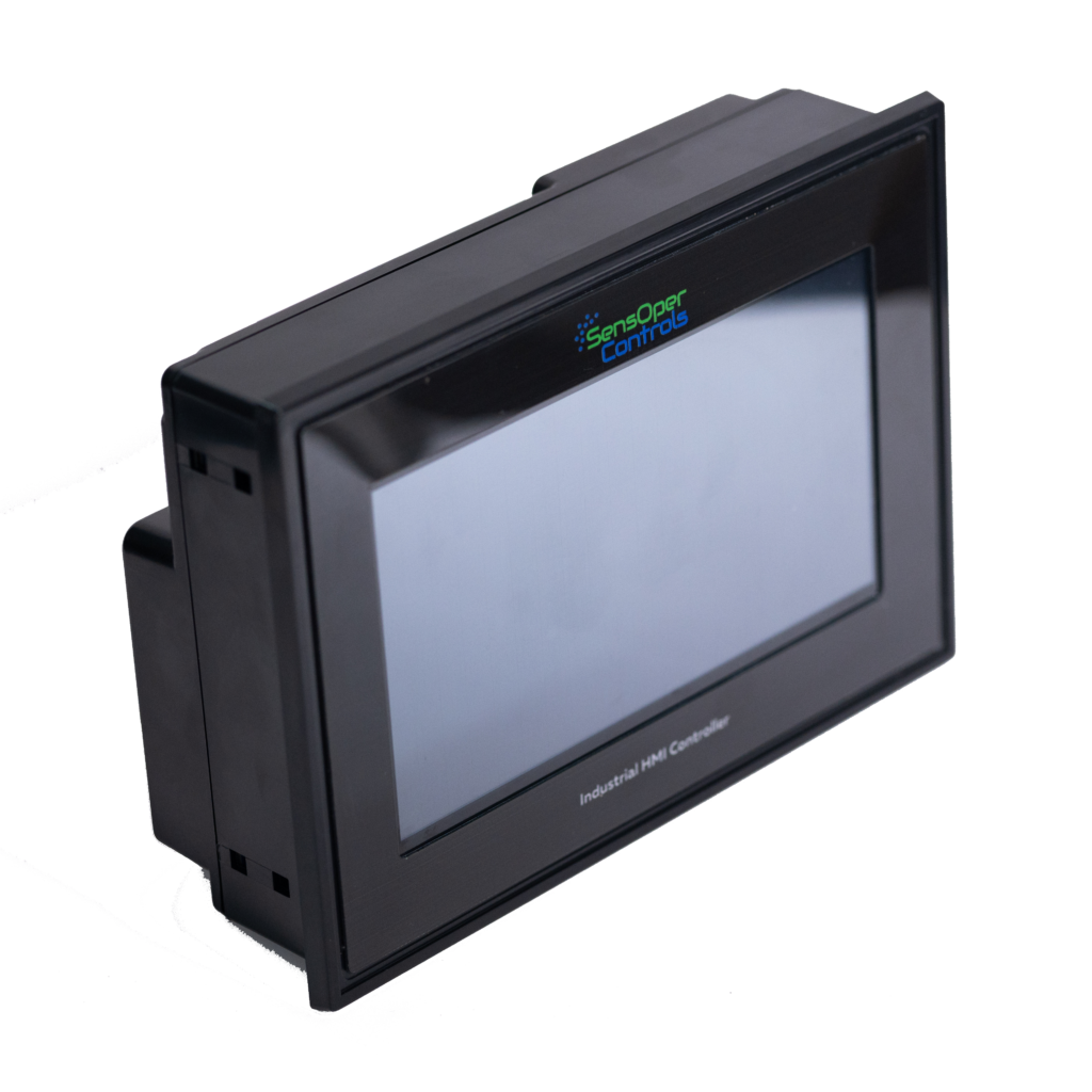
Welcome to the user manual for the RPI-PC-AX8-TO7. The Raspberry Pi HMI is an all-in-one industrial controller based on the powerful Raspberry Pi CM4. It seamlessly integrates a 7-inch touch HMI, PLC functionality, and various connectivity options, making it an ideal solution for IoT applications and industrial gateways.
Features #
- Raspberry Pi CM4
- Broadcom BCM2711 quad-core Cortex-A72 processor
- Integrated 7-inch touch panel with HDMI display
- PLC functionality
- Ethernet and RS-485 connectivity
- Digital Inputs, Analog Inputs, and Transistor Outputs
- DIN-Rail mount for easy installation
Device Configurations #
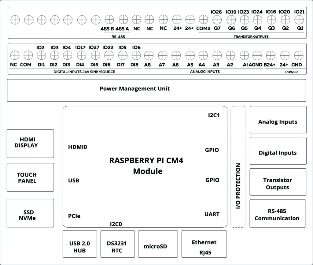
2. Hardware Specifications #
Raspberry Pi CM4
- Processor: Broadcom BCM2711 quad-core Cortex-A72
- Storage: eMMC or micro-SD Card support
- GPIO Pins: Available for external connections
HDMI Display and Touch Panel
- Display Size: 7 inches
- Resolution: 1024×600
- Display Type: IPS screen
- Touch Screen Type: Capacitive Touch Screen
- SCL Pin: IO45
- SDA Pin: IO44
Internal RTC
- RTC Chip: DS3231
- Backup Battery: CR2032
- Interface: I2C
- SCL Pin: GPIO4
- SDA Pin: GPIO44
Ethernet
- Gigabit Ethernet transceiver
- IEEE 1588-2008 compliant
- MDI crossover, Pair skew, and pair polarity correction
USB Device
- USB 2.0 port for updates via RPI boot
- Automatic USB hub disable when a USB cable is plugged in
USB 2.0 HUB
- Onboard USB 2.0 hub
- Connect third-party USB devices
- Current limit switch: approximately 1.2A
3. I/O Configurations #
Digital Inputs #
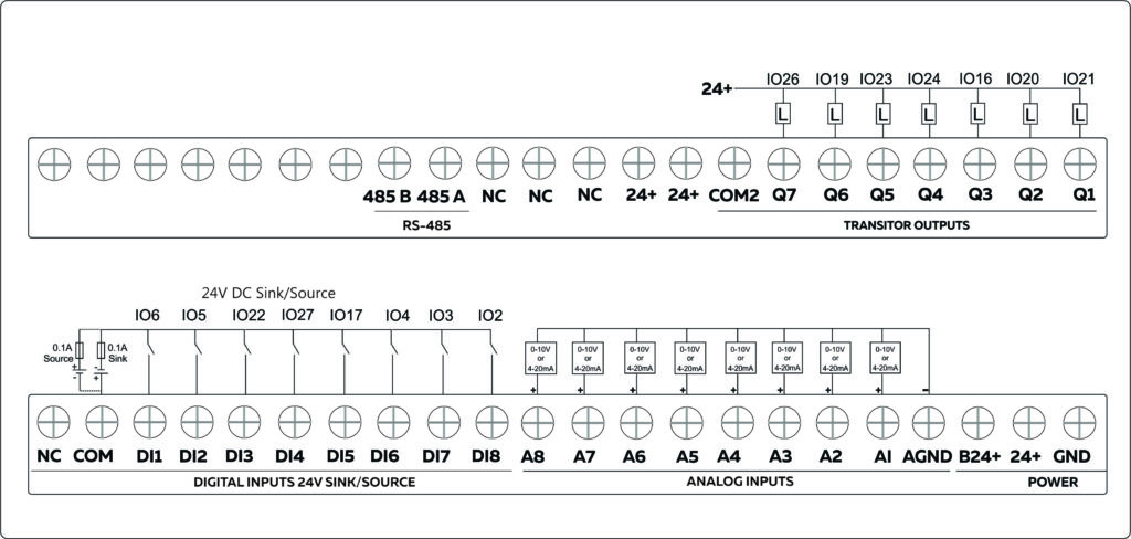
The digital inputs of RPI-PC-AX8-TO7 can be configured as both a Sink and Source connection. The inverse of the Digital Input polar should be supplied to the common terminal. Reading the relevant GPIO of Raspberry Pi CM4 gives the value of the Digital Input. When the inputs are in the OFF state the GPIO goes HIGH, and when the input is in the ON stage, the GPIO goes LOW. Refer to the GPIO allocation table for the digital input GPIO in the Datasheet.

Analog Inputs #
Reading the relevant I2C address of the ADC gives the value of the Analog Input.

0-10V Analog Inputs #
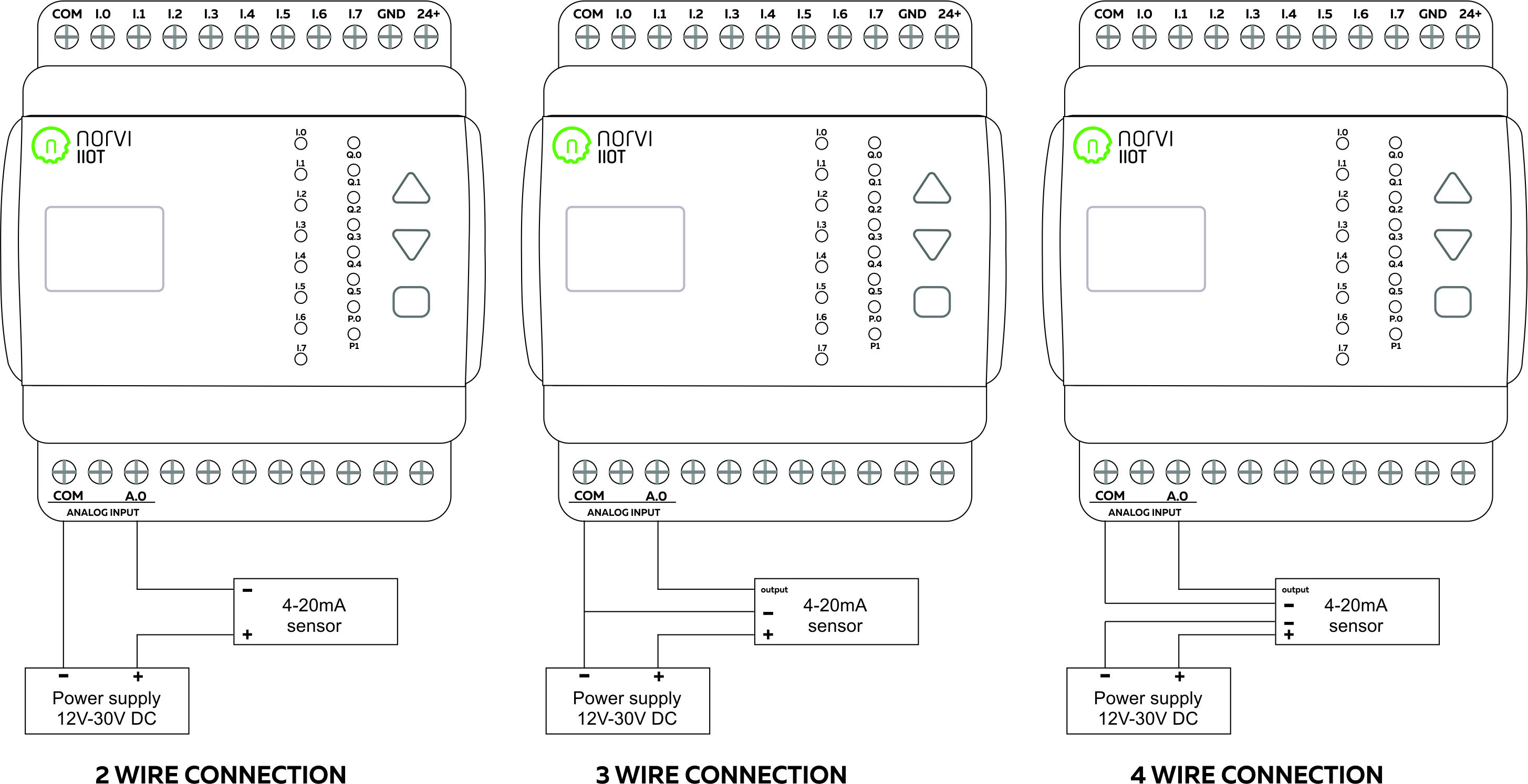
Reading the relevant I2C address of the ADC gives the value of the analog input.

4-20mA Analog Inputs #
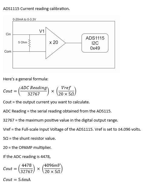
Transistor outputs #
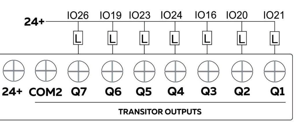
RS-485 Communication #
The UART Connections of RS-485 of RPI-PC-AX8-TO7 series are shared with the UART connections of USB Serial. Configure the RS-485 communication parameters on the requirements of the connected devices. Utilize the GPIO pins on the Raspberry Pi HMI to connect to the RS-485 transceiver. The specific GPIO pins used for RS-485 communication will be determined by the hardware design of the HMI.
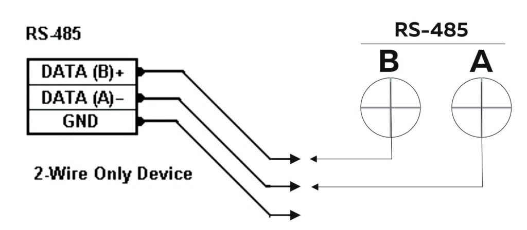
| Driver | SP490CN |
| TX | D15 |
| RX | D14 |
| Flow Control | D18 |
4. Getting Started #
First Power Up #
- Use the micro SD Card or external eMMC for booting.
Raspberry Pi HMI requires an initial boot source to boot the operating system. There are two options for this: using a micro SD card or an external eMMC (Embedded Multimedia Card). The CM4 Lite version does not have on-board eMMC. For that, it is necessary to use a micro SD card. If using a micro SD card, insert the card into the designated slot on the Raspberry Pi HMI. Ensure that the micro SD card contains the necessary boot files and operating system. If using an external eMMC, connect it to the USB HOST connector on the Raspberry Pi HMI. Ensure that the eMMC contains the necessary boot files and operating system.
- Connect the power supply and ensure proper voltage.
Locate the power supply port on the power terminals of the Raspberry Pi HMI. Ensure that you are using the correct power supply with the recommended voltage and current specifications. It’s crucial to provide the correct voltage to prevent potential damage to the Raspberry Pi HMI.
- Power on the Raspberry Pi HMI.
Once the power supply is connected and the boot source (micro SD card or external eMMC) is in place, the Raspberry Pi HMI turns on. The device will begin the boot sequence, and the startup process displayed on the integrated 7-inch touch panel or any connected external display via HDMI.

Default Passwords #
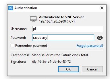
When first powering on the device and trying to access its operating system, it must provide a username and password to log in. “Default Password and Username” is the default login set for the Raspberry Pi HMI.
- User name: pi
- Password: raspberry
5. Functional Testing #
After logging into the system, the displayed interface offers a quick summary of the Raspberry Pi HMI’s Input/output (I/O) status. This interface visually represents the real-time conditions of connected devices, such as sensors and actuators, providing a convenient overview for monitoring and control in an industrial or automation environment.

When analog inputs are connected, the system displays the corresponding high values for those inputs, as illustrated in the figures below.

When digital inputs are connected, the system displays the corresponding high values for those inputs, as illustrated in the figures below.

To obtain the outputs, once the transistor inputs are connected, change the output status to ‘ON’ directly from the interface, as depicted in the figure below.

After establishing the RS485 connection, the next step involves receiving data. Once RS485 is successfully connected, initiate the data transmission process by selecting the ‘RS485’ option directly from the interface. Upon sending the data, the received message will be displayed, showcasing the serial of the recipient, as illustrated in the figure presented below.

6. Programming Environment #
Node-RED Access #
Node-RED is a versatile platform used for programming the Raspberry Pi HMI. The Node-RED version runs within the CPU module of the SENSOPER industrial controller category, featuring specially developed nodes tailored for the Raspberry Pi HMI module. The Node-RED approach is particularly suited for individuals with limited programming knowledge, offering flexibility in adjusting node settings based on user requirements.
Power up and activate #
Navigate to the Application Menu > Internet > Chromium Web Browser, opening the web browser following the path indicated in Figure 1.

In the web browser’s address bar, type http://localhost:1880 and press Enter to access the Node-RED Dashboard, as demonstrated in Figure 2.

Once the Node-RED dashboard is displayed in the web browser tab, click the “>” symbol or press “CTRL + P” to reveal the Toggle Palette. Similarly, click the “<” symbol or press “CTRL + Space” to unveil the Toggle Side Bar, as illustrated in Figure 3.

Implementing and Deploying a Simple Node-RED Program: #
Navigate to the left “Toggle Palette” and scroll down to the “NVI HMI OUT” and “NVI HMI IN” categories. Nodes within these categories are utilized for programming industrial Panel controller modules. In addition, from the “common” category at the top of the “Toggle Palette,” find inputs, outputs, and debug nodes, as indicated in Figure 4. To modify node settings, double-click on the respective node.

Once the Node-RED program is configured, click the “Deploy” button to initiate the program. To access information about a specific node, click the “Book” symbol and then select the desired node, as shown in Figure 5.


