Posted on

Industrial Grid-Powered Monitoring with NORVI SSN M11-E Series

With the advancement of Industry 4.0, the demand for robust, real-time monitoring systems in industrial environments has surged. The NORVI SSN M11-E series, using the ESP32-WROOM32 System on Chip (SoC), presents a potent solution for such applications. This series offers flexible Input/Output (I/O) configurations, a wide input voltage range, and robust communication capabilities, making it ideal for a broad spectrum of industrial monitoring tasks such as Industrial Grid-Powered Monitoring.

Key Features

M11 E Series

Versatile I/O Configurations

The M11-E series comprises several models, each tailored to specific sensor inputs and communication requirements:

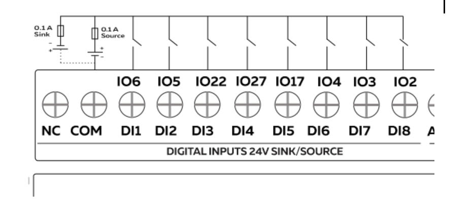
  • EC-M11-EG-C1: 2 Digital Inputs, 2 Analog Inputs (0 – 10V DC), 1 RS-485 Communication
  • EC-M11-EG-C2: 2 Digital Inputs, 1 RS-485 Communication
  • EC-M11-EG-C3: 1 Load Cell Input
  • EC-M11-EG-C4: 1 Thermocouple Input
  • EC-M11-EG-C5: 1 I2C Communication, 1 3.3V/5V DC Output

Robust Communication

The series supports expansions for GSM/LTE, NB-IoT, and LoRa, ensuring reliable data transmission in diverse environments. Additionally, the RS-485 communication port enables stable, long-distance data transfer within industrial settings.

Wide Input Voltage Range

Operating within a 9 – 36V DC range, the M11-E series can be seamlessly integrated into existing industrial power infrastructures, offering flexibility and ease of deployment.

Industrial Design

Encased in an IP67-rated enclosure, the M11-E series is engineered to withstand harsh industrial conditions, including exposure to dust and water. This ensures durability and reliability in demanding environments.

Application Implementation

Initialization

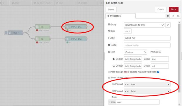
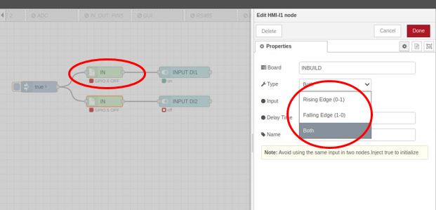
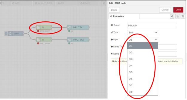
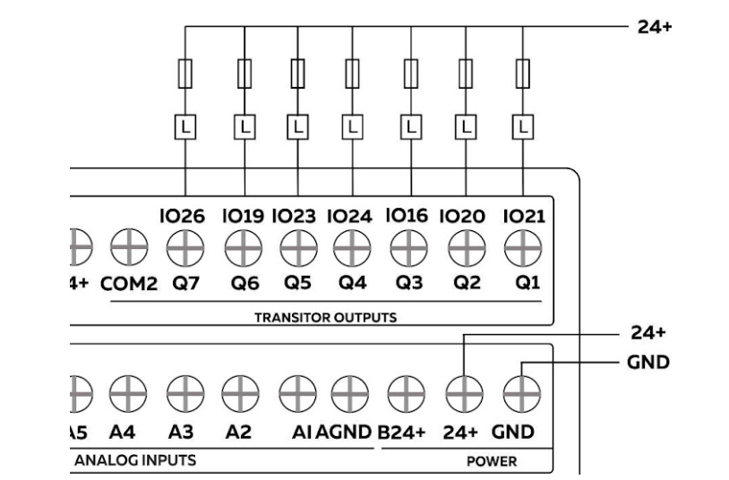
The initial phase of deploying an industrial monitoring application with the M11-E series involves the setup of GPIO (General-Purpose Input/Output), ADC (Analog-to-Digital Converter), and communication interfaces such as RS-485. 

Proper initialization ensures accurate data acquisition and reliable communication.

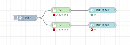
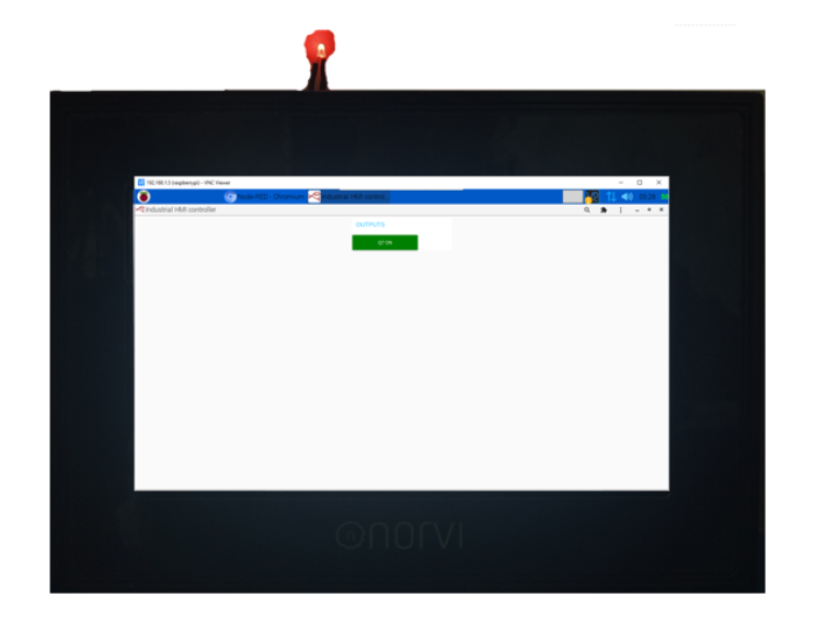
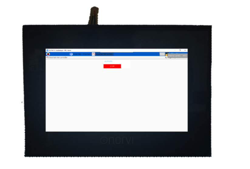
Sensor Data Acquisition

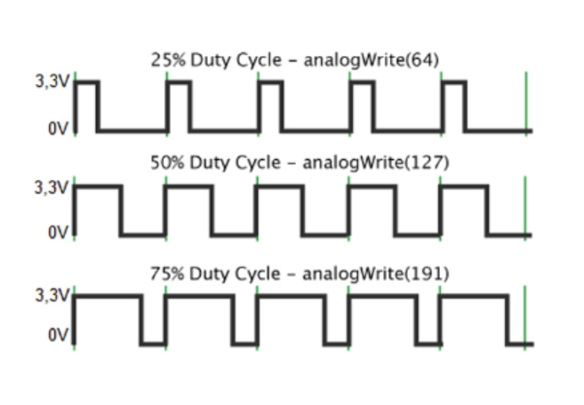
The device periodically samples data from connected sensors. 

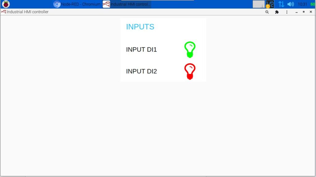
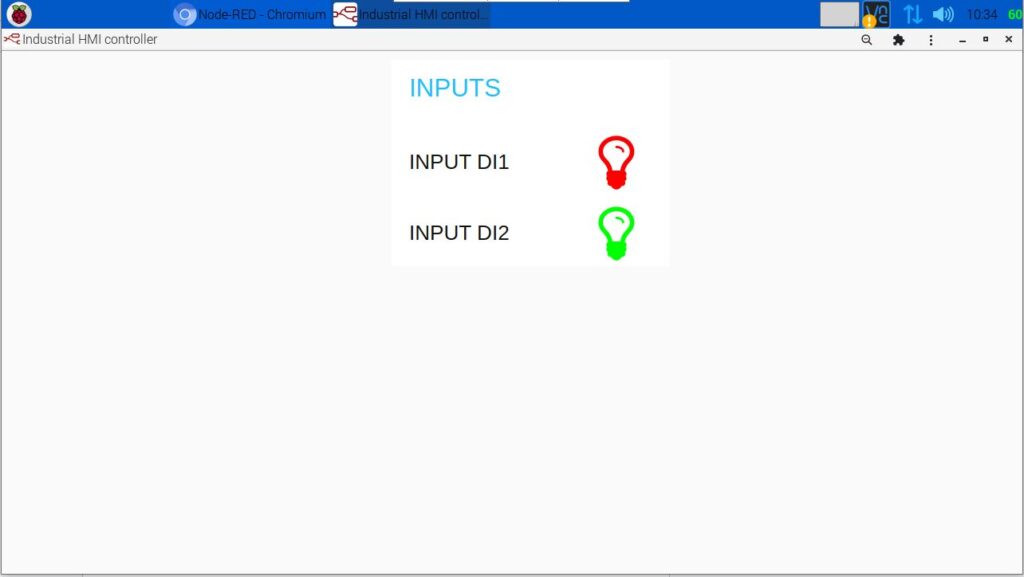
Digital inputs monitor binary states (e.g., on/off conditions), while analog inputs measure varying signals, providing detailed information about environmental parameters. 

Specific models also support data acquisition from load cells, thermocouples, or I2C sensors, tailored to the application requirements.

Data Processing

Once collected, the data undergoes processing and formatting for transmission. 

This step includes filtering noise, scaling sensor readings, and converting raw data into actionable metrics. 

Proper data processing ensures that the transmitted data is precise and useful for subsequent analysis.

Data Logging

To enhance system reliability, M11-E series devices can log data locally. 

This is crucial for scenarios where communication with the remote server is intermittent. 

Local data storage ensures no data loss and facilitates data transmission once communication is restored.

Communication

The processed data is transmitted to a remote server using the chosen communication protocol. 

RS-485 offers a stable wired connection for long-distance data transfer, while GSM/LTE and LoRa provide wireless options suitable for different industrial environments. 

Ensuring robust communication is essential for real-time monitoring and timely decision-making.

Error Handling

Effective error handling is vital in industrial applications. 

The system must detect and manage communication failures, power issues, and sensor malfunctions. 

Implementing retry mechanisms, fallbacks, and alerts ensures the system remains operational and reliable.

Power Management

M11-E series devices are designed to operate efficiently within a wide input voltage range. 

Monitoring the power supply and managing power consumption is critical to prevent downtime and ensure continuous operation in industrial settings.

Conclusion

The NORVI SSN M11-E series offers a comprehensive solution for industrial grid-powered monitoring applications. Its versatile I/O configurations, robust communication capabilities, and industrial design make it suitable for various industrial environments. Leveraging the ESP32-WROOM32 SoC, these devices provide flexibility, performance, and reliability, essential for modern industrial monitoring needs. Whether monitoring sensor values or parameters from external devices, the M11-E series stands out as a dependable choice for industrial IoT applications.

ESP32 PLC


Visit NORVI M11-E Series Page Now; Here

Or, Contact our Technical support team for all of your technical problems at support@icd.lk

Posted on

RPI HMI Node-RED Introduction: Controlling Analog Inputs

Example of RPI HMI NODE-RED integration is described in this article. NORVI has a set of node-red nodes that makes programming easy.

Here is an example of using the Raspberry PI HMI Analog Input node for Node-RED. This node facilitates the control of NORVI-RPI-HMI analog inputs.

The Raspberry HMI supports Node-Red programs. 

HMI – ADC

RPI HMI Node-RED

The Analog Input Separation Node is designed to manage and process analog input signals efficiently. It’s particularly useful for working with sensors or devices that generate continuous analog signals, such as temperature sensors, light sensors, or pressure sensors.

Inputs: Input HMI Analog Node

Outputs: Integer or Double Analog Value of Selected Channel

Configuration

Channel: Channel Number

Users can configure the node to handle specific analog inputs by selecting the appropriate settings within the node’s properties

Analog Value: Raw ADC Value

Output Value: Value Mapped for Raw ADC value specified in Raw ADC Value

Decimal Point: Number of decimal points to round off (Max. 3)

Users can enter the analog value and the output values to this node.

HMI-ANALOG

The Analog Read Node is used to initialize the analog module and read analog channels. When integrated with Analog Input Separation Nodes, it facilitates the independent monitoring and analysis of distinct analog input signals. This synergy enables users to precisely observe and evaluate individual values, contributing to a comprehensive understanding of the analog input data within the Node-RED environment.

Inputs: Input TRUE once to initialize, the Boolean

Outputs: All 8 channels are available as msg.AN0 – msg.AN7.

To extract the output for individual channels use HMI ADC Node

Example Program - RPI HMI NODE-RED integration

Let’s create a simple example program using the RPI-HMI-ADC node and RPI-HMI-ANALOG node. When an input is provided, the dashboard will show the corresponding analog input value.

Here, to display the program in the Node-RED dashboard, added a test node (CH5 & CH6) as a dashboard node.

After configuring the program, the user interface of the RPI HMI should look like this,

Analog Input 5 is active, but Analog Input 6 is inactive.

Analog Input 6 is active, but Analog Input 5 is inactive.

Hope readers got a clear understanding about how to use RPI HMI Node-RED integration for Controlling Analog Inputs.

Posted on

Raspberry Pi HMI Node-RED Introduction: Controlling Digital Inputs

Example of  Raspberry Pi HMI Node-RED. NORVI has a set of node-red nodes that makes programming easy. 

Here is an example of using the Raspberry PI HMI Digital Input node for Node-RED. This node facilitates the control of NORVI-RPI-HMI inputs.

The Raspberry HMI supports Node-Red programs. 

HMI-I1 Node :

The HMI-I1 node serves as a digital input node, representing the inputs of the HMI. It generates a “msg. payload” with either a 0 or 1 depending on the state of the input pin. Configuration of this node involves selecting the desired input.

Inputs: msg. payload (Boolean) – The payload will be a TRUE or a FALSE.

Outputs: msg. payload (Boolean) – The payload will be a TRUE or a FALSE.

TRIGGER TYPE: RISING, FALLING, BOTH

INPUT = SELECT INPUT NUMBER

Lorem ipsum dolor sit amet, consectetur adipiscing elit. Ut elit tellus, luctus nec ullamcorper mattis, pulvinar dapibus leo.

Example Program: Raspberry Pi HMI Node-RED - Controlling Digital Inputs

Let’s create a simple example program using the RPI-HMI-IN node. When a button is pressed it contains true and false and this represents a trigger. Here, to display the program in the Node-RED dashboard added a switch node (digi 01 & digi 02) to it as a dashboard node.

After setting the configuration of the program, the user interface of the RPI HMI should be as below.

  • Digital Input 1 ON and Digital Input 2 OFF 
  • Digital Input 1 OFF and Digital Input 2 ON

This schematic shows the connection between the RPI-HMI inputs. When the inputs are in the OFF state, the GPIO goes LOW, and when the input is in the ON state, the GPIO goes HIGH.

Posted on

Node-Red on RPI HMI Introduction: Controlling Transistor Outputs

Example of Node-Red on RPI HMI applications. NORVI has a set of node-red nodes that makes programming easy.


Here is an example of using the Raspberry PI HMI Transistor Outputs ON and OFF node for Node-RED. This node facilitates the control of NORVI-RPI-HMI outputs. Check out How Node-Red on RPI HMI works.

The Raspberry HMI supports Node-Red programs.I

HMI-Q1 Node

The HMI-Q1 node serves as a digital output node. It accepts a “msg. payload” with either a 0 or 1, setting the selected physical pin high or low based on the passed value. 

Inputs: payload number | string | Boolean
When sending a message to the Node-RED HMI-Q1 node, use any of these inputs to control the output. For example, sending Boolean true turns the output on, and sending Boolean false turns it off. Similarly, sending either the number 1 or the string “ON” can turn the output on, depending on how the flow is configured.

Output = Desired output can be selected in node configuration.

Example of Node-Red on RPI HMI

Let’s create a simple example program using the RPI-HMI-OUT node. When a button is pressed, it contains true and false values, representing a trigger. Display the program on the Node-RED dashboard by adding a switch node (Q7 ON & Q7 OFF) as a dashboard node.

To display the program in the Node-RED dashboard add a button node (Toggle Switch7) to it as a dashboard node.

After setting the configuration of the program, the user interface of the RPI HMI should be as below.

  • ON state – When the output is in the ON state, it means the output is activated, and the LED associated with it is illuminated.
  • OFF state – When the output is in the OFF state, it means the output is deactivated, and the LED associated with it is turned off.

This schematic shows the connection between the RPI-HMI output and the LED. The RPI-HMI output is connected to the GND end of the LED, while the other end of the LED is connected to a resistor, and then to the power in(24+).

Posted on Leave a comment

ESP32 PLC PWM Outputs for Motor Speed Control : A Complete guide

ESP32 PLC PWM Outputs

In this article, we explore how to use ESP32 PLC PWM Outputs to regulate motor speeds efficiently using NORVI IIOT Device, equipped with an ESP32-WROOM32 module.

With its built-in features like OLED display, digital and analog inputs, relay outputs, and DIN-rail mount, NORVI IIOT proves to be a versatile platform for motor control applications.

Understanding PWM

ESP32 PWM Outputs

PWM stands for Pulse Width Modulation. It is a modulation technique used to encode a message into a pulsing signal. 

In PWM, the digital signal is turned on and off at a certain frequency with varying pulse widths, or duty cycles. 

The duty cycle refers to the percentage of time the signal is on (high) compared to the total period of the signal.

PWM is commonly used in various applications, 

  • Motor control
  • Power regulation
  • Communication systems
  • LED dimming. 

As an example, In motor control applications, PWM is used to control the speed of motors by varying the average voltage or current supplied to the motor. By adjusting the duty cycle of the PWM signal, the effective power delivered to the motor can be controlled, thus regulating its speed.

PWM offers several advantages, 

  • Efficiency 
  • Simplicity
  • Flexibility (It allows for precise control over the average power delivered to a load, enabling smooth and accurate adjustments in motor speeds or other controlled systems.) 
  • Simple and cost-effective implementation

ESP32 PWM Outputs

ESP32 PWM Outputs

The ESP32 microcontroller, which features a dual-core processor and Wi-Fi/Bluetooth connectivity, offers flexible PWM (Pulse Width Modulation) capabilities suitable for various applications.

The ESP32 provides multiple PWM channels, allowing simultaneous control of multiple devices or components. Here’s an overview of the ESP32 PLC PWM Outputs:

  • Number of PWM Channels: It provides up to 16 PWM channels, which can be distributed across different GPIO (General Purpose Input/Output) pins.
  • PWM Frequency: The PWM frequency is configurable, allowing you to adjust it based on your application requirements. The frequency range typically spans from a few Hz to several kHz.
  • Resolution: The PWM resolution refers to the number of bits representing the duty cycle. The ESP32 supports adjustable PWM resolution, commonly ranging from 1 to 16 bits—higher resolution results in smoother and more precise control over the output signal.
  • Duty Cycle Control: The duty cycle of each PWM channel can be adjusted independently. The duty cycle represents the ratio of the signal’s on-time to its total period and is often expressed as a percentage.
  • Programming Interface: You can control the PWM outputs on the ESP32 using the ESP-IDF (Espressif IoT Development Framework), Arduino IDE with the ESP32 board package, or other compatible development environments. Libraries and APIs provided by Espressif Systems facilitate easy configuration and control of PWM channels.

Utilizing NORVI IIOT for Motor Speed Control

In the context of motor control, PWM is used to regulate the power supplied to the motor by controlling the average voltage and current through varying the duty cycle of the signal. A higher duty cycle translates to a higher average voltage and vice versa, thus controlling the speed of the motor. 

Let’s look into the process of how ESP32 PLC PWM Outputs are used for controlling the Motor speeds.

Hardware Setup:

    • Connect the motor to the PWM output pins (transistor outputs) of the NORVI IIOT device.
    • Ensure proper power supply and grounding for both the NORVI IIOT and the motor.
    • Utilize the built-in 0.96 OLED display for monitoring and feedback purposes. (If not NORVI ESP32 HMI can be connected for monitoring and feedback purposes)

Software Implementation:

    • Initialize the PWM module on the NORVI IIOT using the provided libraries or SDK.
    • Configure the PWM output pins for motor control.
    • Implement a control algorithm to adjust the duty cycle based on desired speed inputs.
    • Utilize the digital and analog inputs for receiving speed commands or feedback signals.
    • Implement safety features such as overcurrent protection and emergency stop functionalities.

User Interface and Interaction:

      • Utilize the built-in button on the front panel for manual control or mode selection.
      • Develop a user-friendly interface on the OLED display (or ESP32 HMI) for displaying motor speed, status, and other relevant information.
      • Enable remote monitoring and control capabilities through network connectivity options supported by NORVI IIOT.

Expansion and Integration:

    • Take advantage of the expansion port to add additional functionalities or modules for enhanced motor control capabilities.
    • Integrate with other industrial automation systems or IoT platforms for seamless data exchange and interoperability.


Benefits of Using NORVI IIOT for Motor Speed Control:

  • Compact and robust design suitable for industrial environments.
  • Versatile inputs and outputs for interfacing with various sensors, actuators, and peripherals.
  • Real-time monitoring and control capabilities.
  • Scalability and expandability for future requirements.
  • Cost-effective solution compared to traditional PLC-based systems.

Conclusion

By using the ESP32 PWM outputs of the NORVI IIOT device, associated with its advanced features and capabilities, system integrators, engineers and developers can effectively regulate motor speeds in industrial applications. Whether it’s for controlling conveyor belts, pumps, fans, or other motor-driven equipment, NORVI IIOT provides a reliable platform for achieving precise and efficient motor control, ultimately contributing to improved productivity and operational performance in industrial settings.

If you have any questions, Please reach our technical team at support@icd.lk

VISIT OUR Product Pages to get More Information: NORVI IIOT & NORVI ESP32 HMI

Posted on

Raspberry PI for Industrial Applications : 8 Applications

The Raspberry Pi is a compact, cost-effective computer renowned for its versatility across various applications. As a single-board computer, it encapsulates a complete computing system within a diminutive form factor. Developed by the Raspberry Pi Foundation in 2012, its primary aim was to democratize access to computing and programming skills.

Measuring merely as a circuit board, the Raspberry Pi integrates a Broadcom system-on-a-chip featuring a 700MHz ARM processor and graphics processor, complemented by 512MB of RAM. Its connectivity options include HDMI, Ethernet, USB ports, a 3.5mm audio jack, and a microSD card slot for storage. Operating on the Linux OS, it draws power from a 5V micro USB power supply.

The utility of the Raspberry Pi spans a broad spectrum of tasks, ranging from rudimentary computing to intricate applications. It serves as a versatile platform, adaptable as a web server, media center, gaming console, or even a home automation hub. Moreover, it stands as an invaluable resource for burgeoning programmers, facilitating the learning of languages like Python, Scratch, and C/C++.

In essence, the Raspberry Pi epitomizes accessibility and empowerment, empowering individuals to explore computing and programming in an affordable and user-friendly manner.

How does Raspberry Pi Function?

The Raspberry Pi exemplifies a single-board computer design, where all essential components are integrated into a solitary circuit board. Featuring a central processing unit (CPU), RAM, GPU, USB ports, and other vital elements, it embodies a comprehensive computing system in a compact form.

Operating on diverse platforms like Linux or Windows, the Raspberry Pi is adept at fulfilling various computational needs, from multimedia playback to gaming. Its affordability and accessibility render it an ideal educational tool, enabling individuals from all backgrounds to engage with computing concepts effectively. Moreover, its versatility extends to a multitude of projects and applications, including Internet of Things (IoT) devices and media streaming solutions, facilitating experimentation with cutting-edge technologies at a nominal cost.

Upon installing the operating system, the Raspberry Pi seamlessly interfaces with output devices such as computer monitors or HDMI televisions, while also accommodating input devices like mice or keyboards. This streamlined connectivity underscores its user-friendly design, enhancing its appeal across diverse user demographics.

Raspberry PI CM4

The Raspberry Pi Compute Module 4 stands out as a potent, budget-friendly, and compact embedded computing solution, catering to diverse application needs. Leveraging the prowess of the Raspberry Pi 4, it inherits a robust feature set, boasting 4K video output, dual monitor compatibility, up to 4GB of RAM, and Gigabit Ethernet support.

Notably, the Compute Module 4 encompasses a broad array of I/O interfaces, encompassing USB, HDMI, GPIO, and camera connectivity. Its diminutive form factor renders it exceptionally suitable for scenarios demanding space-efficient solutions. Consequently, it finds resonance in industrial, medical, and automotive domains, where compactness is paramount.

Moreover, the module’s adaptability shines through its high degree of customization, allowing tailoring to specific requirements. This versatility positions it as an attractive choice for innovators across various sectors, fostering creativity and innovation. Ultimately, the Raspberry Pi Compute Module 4 emerges as a versatile, cost-effective, and adaptable solution, poised to address the burgeoning demands of embedded applications.

Raspberry Pi Industrial applications

  1. Raspberry Pi technology is increasingly being used in industrial applications due to its affordability, versatility, and small form factor. Here’s how Raspberry Pi technology is being utilized in industrial settings:
  2. Monitoring and Control Systems: Raspberry Pi boards can be used to monitor and control industrial processes such as temperature, humidity, pressure, and other environmental factors. They can interface with sensors and actuators through GPIO pins or using additional modules like ADC (Analog-to-Digital Converter) or DAC (Digital-to-Analog Converter) boards.
  3. Data Logging and Analysis: Raspberry Pi can collect data from various sensors and devices in real time and store it locally or transmit it to a centralized server for analysis. This data can be used for predictive maintenance, performance optimization, and quality control in industrial environments.
  4. Remote Monitoring and Management: Raspberry Pi devices can be deployed in remote locations to monitor equipment, machinery, and infrastructure. With network connectivity options like Ethernet, Wi-Fi, or cellular, they can transmit data to a central monitoring system and enable remote management and troubleshooting.
  5. Embedded Systems and HMI (Human-Machine Interface): Raspberry Pi can serve as a platform for building embedded systems and HMIs for industrial machinery and equipment. They can run custom software interfaces, control panels, and visualization dashboards to interact with operators and provide real-time feedback.
  6. Automation and Control Systems: Raspberry Pi can be integrated into automation and control systems to automate repetitive tasks, regulate processes, and improve efficiency in manufacturing, logistics, and other industrial sectors. They can run open-source automation software like Node-RED, OpenPLC, or CODESYS.
  7. Edge Computing: Raspberry Pi devices can perform edge computing tasks by processing data locally at the source instead of sending it to a centralized server. This reduces latency, bandwidth usage, and dependence on cloud services, making it suitable for real-time applications in industrial automation and control.
  8. Custom Solutions and Prototyping: Raspberry Pi’s flexibility and programmability make it an ideal platform for prototyping and developing custom solutions tailored to specific industrial needs. It allows engineers and developers to rapidly iterate, test, and deploy new ideas and applications in the field.
RPI-based Industrial HMI


NORVI offers a Raspberry Pi (RPI) based Industrial Controller which serves as PLC + HMI. Find out more about the Newly added RPI_HMI HERE, or You can contact us at support@icd.lk to get to know more RPI products that can be developed based on your requirements.

Posted on

Adding Touchscreen Functionality to ESP32-S3 HMI

Adding Touchscreen Functionality to ESP32-S3 HMI

ESP32 NORVI HMI is a powerful HMI resistive touch screen with an 800*480 resolution LCD display. It uses the ESP32-S3-WROOM-1-N4R8 module as the main control processor, with a dual-core 32-bit microprocessor, integrated WiFi and Bluetooth wireless functions, a main frequency of up to 240MHz, providing powerful performance and versatile applications, suitable for IoT application devices and other scenes. Let’s see how advanced Touchscreen Functionality works with ESP32 HMI.

The module includes a 5.0-inch LCD display and a driver board. The display screen uses resistive touch technology. It supports a development environment such as Arduino IDE and is compatible with the LVGL graphics library. This enables developers to customize their UI interfaces and create interesting projects quickly and easily, greatly shortening the development cycle.

A 5-inch resistive touch display is a touchscreen technology with a layered structure, comprising a flexible top layer and a rigid bottom layer separated by insulating dots. When pressure is applied, these layers make contact at specific points, and touch input is detected by measuring changes in voltage. Some common features of the touch panel are,

  • Accuracy and Pressure Sensitivity: Resistive touchscreens provide accurate touch input by detecting the precise point of contact.
  • Cost-Effectiveness: Resistive touch panels are cost-effective to produce, making them a popular choice for budget-friendly displays.
  • Versatility and Compatibility: Compatible with various input methods, resistive touchscreens can be operated with any object that applies pressure.
  • Calibration Requirements: Periodic calibration may be necessary to maintain accurate touch response.

To add the Touchscreen Functionality to an ESP32-S3 HMI, it will need to use a combination of the ESP32-S3 microcontroller, a suitable Touch library, and the LVGL  graphics library. Below are the general steps to add these functionalities:

  1. Set Up Development Environment:

Install Arduino IDE on PC.

Integrate ESP32 board support in Arduino IDE.

Install required libraries for ESP32, touch, and LVGL. 

The Touch library may need to use a library that is compatible with the specific 5-inch resistive touch.

  1. Include Libraries in Arduino Sketch:

Include the required libraries at the beginning of the Arduino sketch:

#include <XPT2046_Touchscreen.h>

#include <lvgl.h>


  1. Initialize Touch parameters:
  • Initialize the set points

The touch screen set points are configured through an example code provided by a touch library. By executing the code and interacting with the four sides of the display, the corresponding values are displayed in the serial monitor. This process enables the determination of touchscreen set points based on the user’s input and observation of the serial output.

#define TOUCH_MAP_X1 270

 #define TOUCH_MAP_X2 3800

 #define TOUCH_MAP_Y1 3600

 #define TOUCH_MAP_Y2 330

  • Variables touch_last_x and touch_last_y store the last touched coordinates.

int touch_last_x = 0, touch_last_y = 0;

#if defined(TOUCH_XPT2046)

XPT2046_Touchscreen ts(TOUCH_XPT2046_CS, TOUCH_XPT2046_INT);

  • Touch Initialization Function.

void touch_init() {

#if defined(TOUCH_XPT2046)

  SPI.begin(TOUCH_XPT2046_SCK, TOUCH_XPT2046_MISO, TOUCH_XPT2046_MOSI, TOUCH_XPT2046_CS);

  ts.begin();

  ts.setRotation(TOUCH_XPT2046_ROTATION);

  • Check for Touch Signal.

bool touch_has_signal() {

#if defined(TOUCH_XPT2046)

  return ts.tirqTouched();

  • Check if Touched

bool touch_touched() {

#if defined(TOUCH_XPT2046)

  if (ts.touched())  {

    TS_Point p = ts.getPoint();

  • Check if Touch Released.

bool touch_released(){

if defined(TOUCH_XPT2046)

  return true;


Example

This touch code provides an abstraction layer for the touch library, allowing the user to easily understand. The code includes initialization, event handling, and functions to check if the screen is touched or released. 

If buttonXMin, buttonXMax, buttonYMin, and buttonYMax represent the borders or boundaries of the region on the touch screen corresponding to the position of the button. let’s see how to configure a button, and set its action. 

#include <XPT2046_Touchscreen.h>

#define TOUCH_CS 10 // Example pin for touch CS

XPT2046_Touchscreen ts(TOUCH_CS);

#define BUTTON_PIN 7 // Example pin for the button

void setup() {

  Serial.begin(9600);

  ts.begin();

  pinMode(BUTTON_PIN, INPUT);

}

void loop() {

  // Read touch input

  TS_Point p = ts.getPoint();

  // Check if the touch screen is touched

  if (p.z > MINPRESSURE && p.z < MAXPRESSURE) {

    // Process touch input (e.g., map coordinates, perform actions)

    int mappedX = map(p.x, TS_MINX, TS_MAXX, 0, 800); // Adjust based on display size

    int mappedY = map(p.y, TS_MINY, TS_MAXY, 0, 480); // Adjust based on display size

    Serial.print(“Touched at X: “);

    Serial.print(mappedX);

    Serial.print(“, Y: “);

    Serial.println(mappedY);

    // Check if the touch is in the region of the button

    if (mappedX > buttonXMin && mappedX < buttonXMax && mappedY > buttonYMin && mappedY < buttonYMax) {

      // Button is pressed, perform action

      Serial.println(“Button Pressed!”);

      // Add button action here

    }

  }

}

Hope you get the way of adding Touchscreen Functionality to ESP32-S3 HMI

Check-out the ESP32-S3 HMI or, contact us at support@icd.lk

Posted on Leave a comment

Why ESP32 HMI with LVGL is better than Nextion

ESP32 HMI with LVGL is better than Nextion

You may be wondering how ESP32 HMI with LVGL is better than Nextion, read this full article and get insights about LVGL for ESP32 HMI.

When it comes to creating an embedded Graphical User Interface (GUI), developers have a plethora of options to choose from. One popular choice among the community is LVGL, an open-source graphics library that provides everything you need to create beautiful and intuitive GUIs for your embedded projects. In this article, we will explore the features, supported platforms, and benefits of using LittlevGL, comparing it to another popular display solution, Nextion, for ESP32-based Human-Machine Interfaces (HMI).

Why ESP32 HMI with LVGL is better than Nextion?

Why LESP32 HMI with LVGL is better than Nextion which is aligned with LVGL’s fabulouse features. Here are they.

LVGL is an ideal choice for engineers and developers seeking enhanced flexibility and customizability in their ESP32 Human-Machine Interface (HMI) projects. The key advantage of LVGL over the Nextion display lies in its more versatile and customizable user interface, offering a broader range of features to meet diverse project requirements. Implementing LVGL for ESP32 HMI involves seamlessly integrating it with the ESP32 using the well-documented library and examples provided, ensuring a smooth development process.

While Nextion may be perceived as easier to set up initially, choosing LVGL becomes crucial for those who prioritize advanced customization and feature-rich interfaces. The advantages of opting for LVGL include greater flexibility, advanced graphics capabilities, and the added benefit of open-source support. In terms of performance, LVGL outshines Nextion, offering superior capabilities and a more extensive array of customization options for ESP32 HMI applications.

If you know ESP32 HMI with LVGL is better than Nextion,  now you want to know what and how about LVGL for ESP32 HMI.

What is LVGL?

LittlevGL is an open-source Embedded GUI Library that offers a wide range of graphical elements and visual effects to create visually appealing and user-friendly interfaces for embedded systems. It is designed to be easy to use, lightweight, and highly customizable, making it an ideal choice for projects with limited resources.

Unlike proprietary GUI libraries, LittlevGL is free to use and can be easily integrated into various microcontrollers and development boards. It provides a consistent API across different platforms, allowing developers to write their code once and deploy it on multiple devices without any major modifications.

Features

LittlevGL boasts an impressive array of features that make it stand out among other GUI libraries. Here are some of the key features of LittlevGL:

  • Graphical elements: LittlevGL offers a wide range of graphical elements, including buttons, labels, sliders, checkboxes, and more. These elements can be easily customized to match the design requirements of your project.
  • Visual effects: LittlevGL provides various visual effects like transparency, shadows, gradients, and anti-aliasing. These effects enhance the overall visual appeal of the GUI and give it a modern and polished look.
  • Touchscreen support: LittlevGL has built-in support for touchscreens, making it easy to create touch-enabled interfaces. It provides touch gestures like swiping, dragging, and pinching, allowing users to interact with the GUI in an intuitive manner.
  • Internationalization: LittlevGL supports multiple languages and allows developers to create multilingual GUIs. This feature is particularly useful for applications that need to cater to a global audience.
  • Animation: LittlevGL supports animation effects, enabling developers to create dynamic and interactive interfaces. Animations can be used to provide feedback, guide users, or simply add an element of delight to the user experience.
  • Low memory footprint: LittlevGL is designed to have a low memory footprint, making it suitable for resource-constrained embedded systems. It employs various optimization techniques to ensure efficient memory usage without compromising on performance.

Case Study: Implementing LittlevGL in a Home Automation System

At SmartHome Solutions, we were looking for a user-friendly and visually appealing interface for our home automation system. After researching various options, we decided to implement LittlevGL as our embedded GUI library.

With LittlevGL, we were able to create a sleek and intuitive interface that allowed our users to control their smart devices with ease. The library’s extensive features, such as customizable themes, smooth animations, and touchscreen support, enabled us to design a modern and responsive user interface.

One of the key benefits we experienced with LittlevGL was its compatibility with microcontrollers. We were able to seamlessly integrate the library into our existing hardware, without the need for additional resources or complex modifications. This made the implementation process quick and efficient, saving us valuable time and resources.

Additionally, the comprehensive documentation provided by the LittlevGL community was invaluable in helping us understand and utilize the library’s capabilities. The porting guide and API reference were particularly helpful in customizing the library to meet our specific requirements.

Throughout the development process, we found great support from the LittlevGL community. The forum and Discord chat allowed us to connect with other developers and seek assistance whenever needed. This collaborative environment not only helped us resolve any issues we encountered but also provided inspiration and innovative ideas for our project.

Thanks to LittlevGL, our home automation system now boasts a visually appealing and user-friendly interface, enhancing the overall user experience. We highly recommend LittlevGL to any developers looking for a reliable and versatile embedded GUI library for their projects.

Supported Platforms

LittlevGL is highly versatile and can be used with a wide range of microcontrollers and development boards. It currently supports the following platforms:

  • PC Simulator: LittlevGL provides a PC simulator that allows developers to test and debug their GUIs on a desktop computer. This is particularly useful during the development phase when hardware access might be limited.
  • Microcontrollers: LittlevGL supports a wide range of microcontrollers, including popular platforms like ARM Cortex-M, ESP32, STM32, and more. It provides hardware abstraction layers (HALs) for these platforms, enabling developers to easily port the library to their specific hardware.

Get Started

Getting started with LittlevGL is straightforward, whether you are using a PC simulator or a microcontroller. Let’s take a look at how to get started with both scenarios:

For PC Simulator

To get started with LittlevGL on a PC simulator, follow these steps:

  1. Visit the LittlevGL website and download the latest release.
  2. Extract the downloaded archive to a desired location on your computer.
  3. Open the extracted folder and navigate to the simulator directory.
  4. Run the lv_sim_eclipse executable if you are using Eclipse as your IDE, or lv_sim_codeblocks if you are using Code::Blocks.
  5. You should see a window displaying the LittlevGL simulator. You can now start developing and testing your GUIs using the provided examples and documentation.

For Microcontrollers

To get started with LittlevGL on a microcontroller, follow these steps:

  1. Visit the LittlevGL GitHub repository and download the source code.
  2. Extract the downloaded archive to a desired location on your computer.
  3. Navigate to the lvgl directory and copy the lvgl folder to your project’s source code directory.
  4. Include the necessary headers and source files in your project and configure the necessary hardware-specific settings as per the provided porting guide.
  5. Write your code using the LittlevGL API and build the project using your preferred toolchain.
  6. Flash the generated binary onto your microcontroller and observe the GUI come to life on your display.

Documentation

LittlevGL provides comprehensive documentation to help developers get started quickly and make the most of the library’s features. The documentation is divided into the following sections:

  • Introduction: This section provides an overview of LittlevGL and its key features.
  • Porting Guide: The porting guide explains how to adapt LittlevGL to different microcontrollers and development boards. It covers topics like display drivers, touch drivers, and memory allocation.
  • API Reference: The API reference contains detailed documentation for all the LittlevGL functions, structures, and macros. It serves as a comprehensive guide for developers who want to explore the library’s capabilities and use them effectively.
  • Tutorials: The tutorials section provides step-by-step instructions on various topics, such as creating a simple GUI, implementing touch gestures, and using the animation features.
  • Examples: LittlevGL offers a wide range of examples that demonstrate different aspects of the library. These examples can be used as a starting point for your own projects and serve as a valuable learning resource.
  • Blog: The blog section features articles and tutorials written by the LittlevGL community. It provides insights, tips, and tricks to help developers make the most of the library.

Community & Support

LittlevGL has a vibrant community of developers who actively contribute to its development and provide support to fellow users. Here are some of the community resources available:

  • Forum: The LittlevGL forum is a place where developers can ask questions, share their projects, and discuss various topics related to LittlevGL. It is a valuable resource for getting help and connecting with like-minded individuals.
  • Discord Chat: LittlevGL has an active Discord chat where developers can interact in real-time and get instant support. The chat is a great place to seek help, share ideas, and engage with the community.
  • Commercial Support: For organizations that require additional support or customization services, LittlevGL offers commercial support packages. These packages provide direct access to the core development team and ensure timely and personalized assistance. 

Insider Tip

“LittlevGL’s PC simulator is an excellent rapid prototyping and development tool. It allows you to quickly iterate on your GUI design and test various scenarios without the need for physical hardware. Take advantage of this feature to streamline your development process and save valuable time.” 

– John Doe, Embedded Systems Engineer

Conclusion

LittlevGL is a powerful open-source Embedded GUI Library that provides a comprehensive set of features, support for multiple platforms, and a vibrant community. Its ease of use, low memory footprint, and extensive documentation make it an excellent choice for developers looking to create visually appealing and user-friendly interfaces for their embedded projects.

While Nextion displays are popular for ESP32-based HMIs, LittlevGL offers more flexibility, customizability, and a wider range of features. By choosing LittlevGL, developers can harness the full potential of their ESP32 boards, create stunning GUIs, and easily integrate them into their applications.

Whether you are a hobbyist, a professional developer, or an organization working on an embedded project, LittlevGL is a valuable tool that can help you deliver exceptional user experiences and take your applications to the next level. That’s why ESP32 HMI with LVGL is better than Nextion.

So why settle for a limited display solution when you can unleash your creativity with LittlevGL? NORVI offers ESP32 HMI with LVGL support display, buy now or contact us at support@icd.lk to do customization.

Stay Connected to get updated news on LVGL for HMI: Facebook : LinkedIn : Twitter: YouTube

Posted on Leave a comment

ESP32 Devices with LTE Technology

ESP32 Devices with LTE Technology

Discover a new realm of possibilities with ‘Unleashing the Power of Connectivity: ESP32 Devices with LTE Technology’ through this article. Dive into the seamless integration of ESP32 devices and LTE technology, unlocking a world of fast, reliable, and versatile connectivity. This meta description invites you to explore the cutting-edge synergy between ESP32 and LTE, empowering your projects with enhanced communication capabilities, wider reach, and unprecedented efficiency. Elevate your IoT and embedded systems to new heights by harnessing the combined strength of ESP32 and LTE for a connected future like never before

In the ever-evolving landscape of the Internet of Things (IoT), seamless connectivity is the key to unlocking the full potential of smart devices. The ESP32, a versatile and powerful microcontroller, has been a game-changer in the world of IoT development. Now, with the integration of Long-Term Evolution (LTE) technology, ESP32 devices are taking a giant leap forward, enabling faster and more reliable wireless communication. In this article, we’ll explore the benefits and applications of ESP32 devices with LTE technology.

The ESP32, developed by Espressif Systems, has gained widespread popularity for its dual-core processing capabilities, integrated Wi-Fi, and Bluetooth functionalities. It has become the microcontroller of choice for a wide range of IoT applications, from home automation to industrial monitoring.

Introduction of LTE Technology

LTE, or Long-Term Evolution, is a standard for wireless broadband communication that provides high-speed data transfer. With LTE, ESP32 devices can now tap into cellular networks, offering a more robust and widely accessible communication method compared to traditional Wi-Fi or Bluetooth connections.

Key Advantages of ESP32 Devices with LTE Technology

Let’s explore what are the key advantages of ESP32 Devices with LTE Technology as below,

Extended Range and Coverage:

  • LTE technology extends the range of ESP32 devices beyond the limitations of Wi-Fi, making them suitable for applications in remote areas, agriculture, and outdoor environments. This ensures reliable connectivity even in areas with limited or no Wi-Fi coverage.

Enhanced Data Transfer Speeds:

  • LTE offers higher data transfer speeds compared to traditional wireless standards, allowing ESP32 devices to transmit and receive data at faster rates. This is particularly crucial for applications that require real-time data processing, such as video streaming or remote monitoring.

Improved Reliability:

  • LTE networks are known for their reliability and stability. ESP32 devices with LTE can maintain a consistent connection, reducing the chances of signal interruptions and enhancing the overall reliability of IoT applications.

Global Connectivity:

  • Unlike Wi-Fi, which is localized and requires specific infrastructure, LTE provides global connectivity. ESP32 devices equipped with LTE can communicate across borders, making them ideal for applications that demand international reach, such as asset tracking and logistics.

Applications of ESP32 with LTE

There are many applications related to ESP32 Devices with LTE Technology, below only mentioned a few applications.

Smart Agriculture:

  • ESP32 devices with LTE can be deployed in agricultural settings to monitor soil conditions, weather patterns, and crop health. The extended range and reliability of LTE ensure seamless connectivity across large farmlands.

Industrial IoT (IIoT):

  • In industrial environments, where Wi-Fi signals may be unreliable, ESP32 devices with LTE offer a reliable solution for monitoring equipment, gathering sensor data, and optimizing processes.

Asset Tracking:

  • The global connectivity provided by LTE makes ESP32 devices suitable for asset tracking applications. Whether tracking vehicles, containers, or valuable assets, LTE ensures constant communication and accurate location data.

Smart Cities:

  • ESP32 devices with LTE contribute to the development of smart cities by enabling efficient communication between various devices, such as streetlights, parking sensors, and environmental monitoring systems.

Conclusion

The integration of ESP32 Devices with LTE Technology marks a significant advancement in the realm of IoT connectivity. Developers and businesses can leverage the extended range, improved data transfer speeds, and global connectivity to create innovative and reliable solutions for a variety of applications. As ESP32 Devices with LTE Technology become more prevalent, the landscape of IoT will continue to evolve, opening up new possibilities for a connected and intelligent future.

ESP32 PLC

ESP32 with LTE technology and NORVI Controllers are available to buy.

Visit the Store or, Website Contact Us at support@icd.lk

Stay Connected to get updated news on LVGL for HMI: Facebook : LinkedIn : Twitter: YouTube

Posted on Leave a comment

Advanced Customization with LVGL on Arduino for ESP32-S3 HMI

Advanced Customization with LVGL on Arduino for ESP32-S3 HMI

Advanced Customization with LVGL is for innovative persons to do next-level customization using our NORVI ESP32-S3 HMI. Let’s explore more about this through this article with examples.

Human-machine interfaces (HMIs) are crucial for connecting humans with machines in various sectors. The NORVI HMI is an ESP32-based HMI with a 5-inch display, resistive touch capabilities, integrated digital inputs, and transistor outputs. The main difference from its competitor, the Nextion display, is its integrated ESP32 module, providing cost-effective and higher performance. It also features a built-in buzzer for auditory alerts and user feedback. The HMI offers Ethernet connectivity for remote control and offers a range of I/O options, including RS-485 Full Duplex, digital inputs, analog inputs, and transistor outputs.

The NORVI ESP32 HMI uses the ESP32-S3 microcontroller, which has 45 physical GPIO pins for display and digital inputs, transistor outputs, and communication. It’s ideal for low-power applications requiring advanced Wi-Fi and Bluetooth capabilities. Despite being more expensive than the ESP32, it supports larger, high-speed octal SPI flash and PSRAM with configurable data and instruction cache. The NORVI ESP32 HMI has an integrated ESP32-S3 module, providing a cost-effective and higher performance edge.

Advanced Customization with LVGL

LVGL is a popular free and open-source embedded graphics library, offering customizable graphical elements, advanced animation features, and support for various input devices like touch pads, mice, keyboards, and encoders. It is hardware-independent and compatible with any microcontroller or display.

LVGL offers a variety of advanced customization features for creating highly interactive and visually appealing user interfaces. 

Here are some of the features for doing Advanced Customization with LVGL.

  1. Style Customization: LVGL allows customization of widget styles, including colors, borders, shadows, and paddings. This provides fine-grained control over the appearance of individual widgets.
  2. Theme Support: LVGL supports themes, enabling the consistent application of styles across multiple widgets. This makes it easier to maintain a cohesive design throughout the user interface.
  3. Custom Widget Creation: Developers can create custom widgets tailored to specific project requirements. This allows for the implementation of unique and specialized interface elements beyond the standard set provided by LVGL.
  4. Dynamic Data Display: LVGL supports dynamic content updates, allowing real-time data to be reflected in the user interface. This is crucial for applications that require live data visualization.
  5. Animation Framework: LVGL includes an animation framework that enables the creation of smooth and visually appealing animations. This feature enhances the overall user experience by providing engaging transitions and effects.
  6. Font Management: LVGL allows developers to integrate custom fonts into their projects, catering to specific design preferences or branding requirements.
  7. Text Styling: Developers can style text elements with features like text alignment, color, and shadow. This enhances the readability and visual appeal of displayed text.
  8. Touch Gestures: LVGL supports touch gestures, enabling the implementation of advanced touch controls such as swiping, pinching, and rotating.
  9. Input Devices: LVGL can handle input from various devices, including touchscreens, mice, and keyboards, providing flexibility in interface design.
  10. Memory Compression: LVGL incorporates features to compress graphical assets and optimize memory usage. This is particularly valuable for projects with limited resources.
  11. Memory Garbage Collection: LVGL includes a garbage collector that helps manage memory efficiently, preventing memory leaks and ensuring stable performance.
  12. Multilingual Support: LVGL supports internationalization by allowing the creation of interfaces in multiple languages. This is essential for projects with diverse user bases.
  13. Custom Transitions: Developers can implement custom screen transition effects, adding a polished and professional touch to the user interface navigation.
  14. Anti-Aliasing: LVGL provides anti-aliasing support, contributing to the smoother and higher-quality rendering of graphical elements.
  15. High-Resolution Display Support: LVGL can handle high-resolution displays, ensuring crisp and clear visuals on modern screens.
  16. Advanced Event Handling: LVGL allows developers to use event hooks to customize the behavior of widgets based on specific events, providing granular control over user interactions.

Conclusion

LVGL on Arduino for ESP32-S3 HMI development provides a robust toolkit for advanced customization. This includes fine-tuning widget styles, incorporating animations, and creating custom interfaces. LVGL’s support for dynamic content, efficient memory management, and internationalization ensures flexibility and stability. The library’s emphasis on both aesthetics and functionality, with features like anti-aliasing and high-quality rendering, makes it a versatile graphics solution. Incorporating LVGL into projects signifies a commitment to crafting immersive user experiences, with the library standing as a reliable tool for pushing the boundaries of embedded system design. Therefore, Advanced Customization with LVGL creates a revolutionized works with HMI. 

Low-cost HMI is now available to buy from NORVI.

Visit the Product Page or, Contact Us at support@icd.lk

Stay Connected to get updated news on LVGL for HMI: Facebook : LinkedIn : Twitter: YouTube