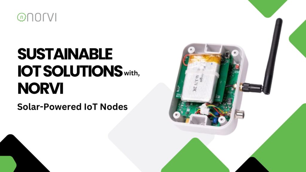
In the evolving landscape of Internet of Things (IoT) technology, sustainability is becoming increasingly important. NORVI offers Innovative Sustainable IoT Solutions that integrate solar power with IoT technology to address the challenges of remote and off-grid deployments.
This article explores NORVI’s solar-powered IoT nodes, focusing on the M11-B and M12-B models, their applications, and their impact on sustainability.
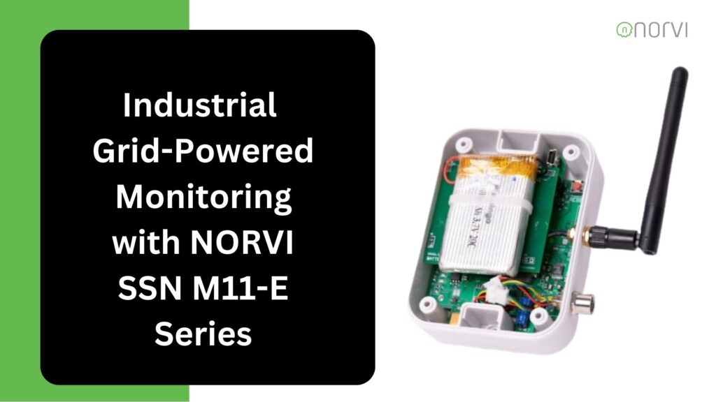
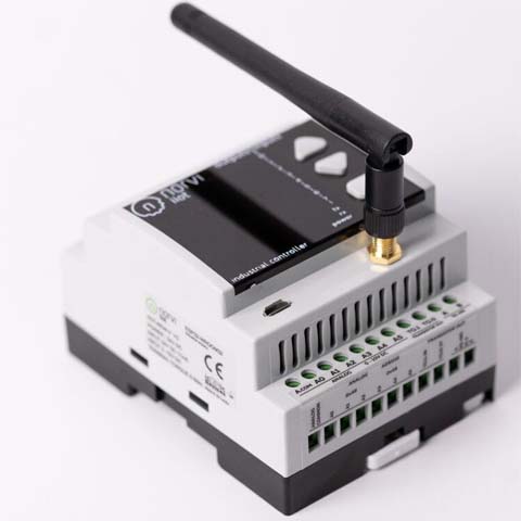
ESP32-based Solar Charging M11-B
- Core Technology: ESP32-WROOM32 Module
The M11-B utilizes the ESP32-WROOM32, which provides dual-core processing power and integrated WiFi connectivity, ensuring high performance and efficient data handling.
- Power Supply: Battery-Powered with Solar Charging
Designed to operate continuously in remote areas, the M11-B features a rechargeable battery complemented by solar charging, ensuring sustained energy supply and reduced maintenance.
- Connectivity: WiFi
The device supports standard WiFi connectivity, facilitating seamless integration with cloud platforms and enabling real-time data transmission.
- Power Output: 12V DC Power Output
The M11-B includes a 12V DC power output to support external sensors and additional peripherals, enhancing its versatility.
- Durability: IP67 Rated Enclosure
With an IP67 rating, the M11-B is protected against dust and water ingress, making it suitable for harsh environmental conditions.
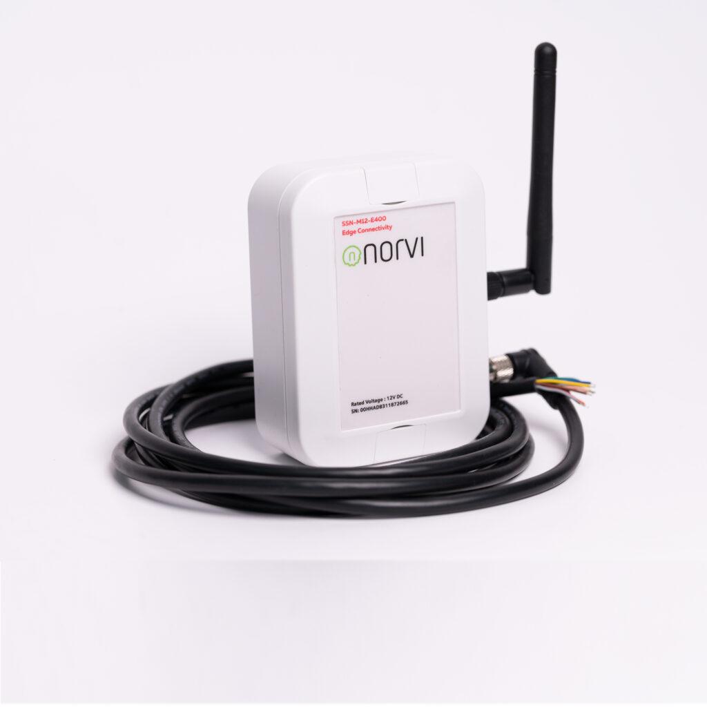
STM32L1-based Solar Charging M12-B
- Core Technology: STM32L1 Series MCU
The M12-B is based on the STM32L1 Series microcontroller, which is optimized for ultra-low power consumption while delivering efficient processing capabilities.
- Power Supply: Battery-Powered with Solar Charging
The M11-B, the M12-B features a battery with solar charging capabilities, ensuring reliable operation in remote and off-grid locations.
- Connectivity: Multi-Protocol Support
The M12-B supports LoRa, Zigbee, NB-IoT, and GSM-LTE, providing versatile connectivity options for various network requirements.
- External Connections: Wired External Connections
Facilitates integration with additional hardware and peripherals, broadening its application scope.
- Power Output: 12V DC Power Output
Includes a 12V DC output for powering external sensors, extending the device’s functionality.
- Durability: IP67 Rated Enclosure
The robust IP67-rated enclosure ensures durability against dust and moisture, suitable for challenging conditions.
Application of Solar-Powered IoT Nodes
Solar-Powered Applications:
- Environmental Monitoring: These nodes are ideal for remote environmental monitoring, including weather stations and pollution sensors, where reliable power is essential.
- Smart Agriculture: Used for monitoring soil conditions, climate, and crop health in agricultural settings without the need for grid power.
- Energy-Efficient Solutions: Utilized in applications where energy efficiency and sustainability are critical, reducing reliance on traditional power sources.
Industrial and Urban Use Cases:
- Smart City Infrastructure: Suitable for smart metering, traffic monitoring, and other urban applications requiring consistent data collection and transmission.
- Industrial IoT: Employed in equipment monitoring, condition tracking, and environmental sensing in industrial environments.
- Remote Installations: Perfect for areas with no access to electrical infrastructure, providing autonomous operation and continuous data logging.
Impact of Solar-Powered Devices
Sustainability:
- Extended Operational Life: The combination of solar charging and battery backup minimizes the need for frequent maintenance and battery replacements.
Operational Efficiency:
- Autonomous Functionality: Enables long-term, autonomous operation in remote locations, enhancing data collection and system reliability without the need for manual intervention.
NORVI is at the forefront of integrating sustainable practices into IoT technology. By offering solar-powered solutions like the M11-B and M12-B, NORVI contributes to greener technology solutions and supports the global shift towards renewable energy. These devices align with sustainability goals by reducing dependency on traditional power sources and promoting energy-efficient operations.
Limitations
- Environmental Dependence: Solar Power Variability
Performance may be affected by weather conditions and geographic location, potentially limiting energy availability in certain environments.
- Initial Cost: Higher Initial Investment
The upfront cost of solar-powered systems can be higher compared to traditional powered devices, though the long-term benefits often outweigh this initial investment.
Conclusion
NORVI’s solar-powered IoT nodes, the M11-B and M12-B, represent a significant advancement in sustainable technology. By integrating solar energy with advanced microcontrollers and versatile connectivity options, these devices offer robust solutions for a wide range of applications. Their ability to operate autonomously is valid in this digital world incorporation with sustainability.
Contact us at [email protected] for more information.