Posted on Leave a comment

Taking IoT to the Next level Programmable Devices

NORVI IIOT - Arduino Compatible PLC

The world of industrial automation is witnessing a significant shift towards connectivity and data-driven decision-making. In this era of Industry 4.0, the Arduino platform has emerged as a popular choice for rapid prototyping and DIY projects due to its ease of use and vast community support. NORVI IIOT takes this compatibility to new heights by seamlessly integrating Arduino’s simplicity with the capabilities required for industrial automation, making it a compelling solution for diverse applications.

NORVI IIOT: Arduino Compatibility Amplified

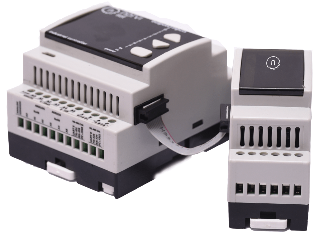
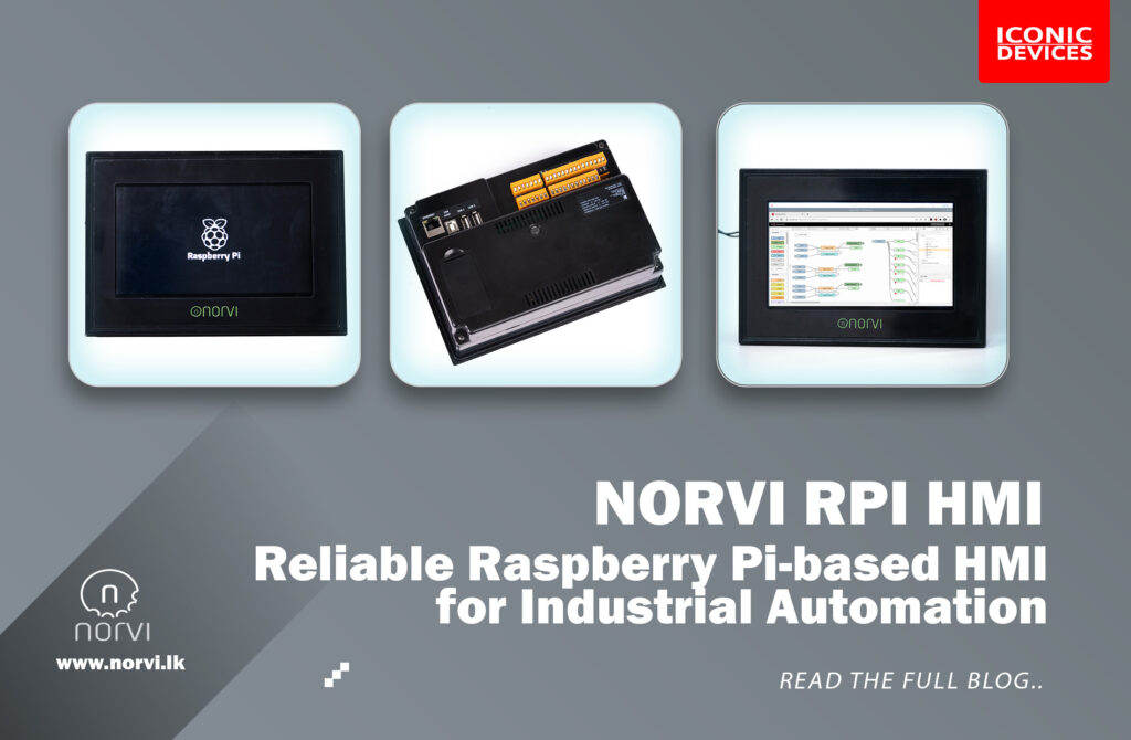
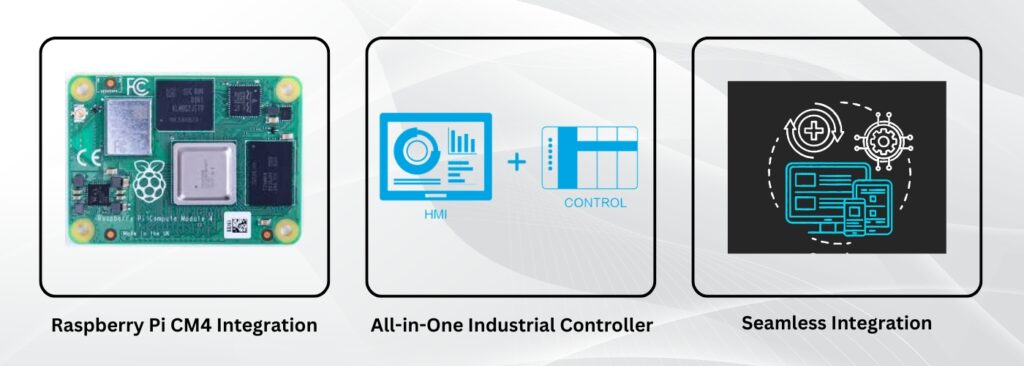
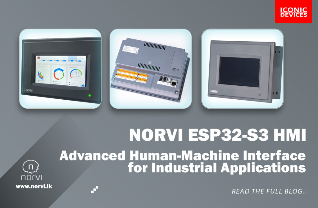
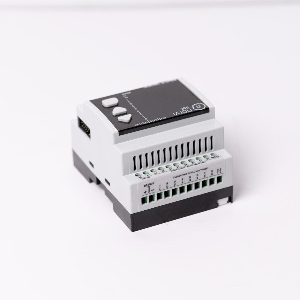
NORVI IIOT is a revolutionary hardware platform that embraces Arduino compatibility while addressing the specific requirements of industrial automation. It combines the openness and flexibility of Arduino programming with the robustness and reliability necessary for industrial environments, empowering engineers and developers to create advanced automation solutions efficiently.

Key Features and Benefits

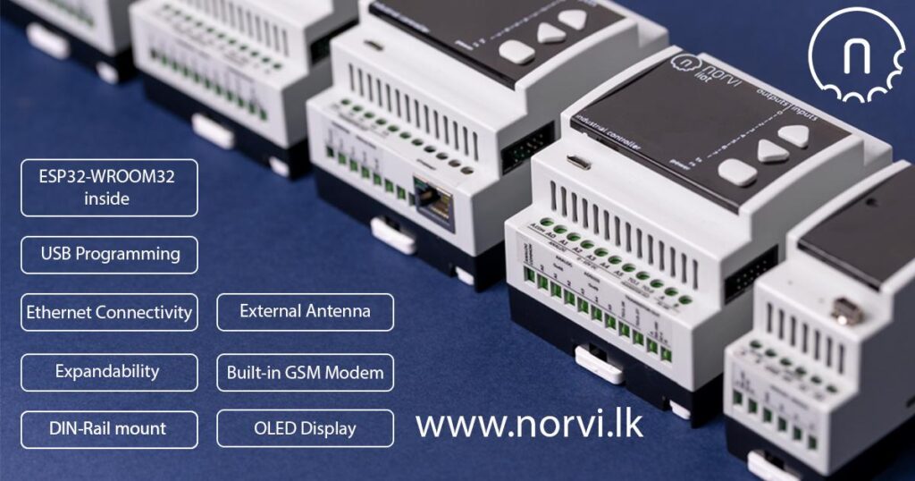
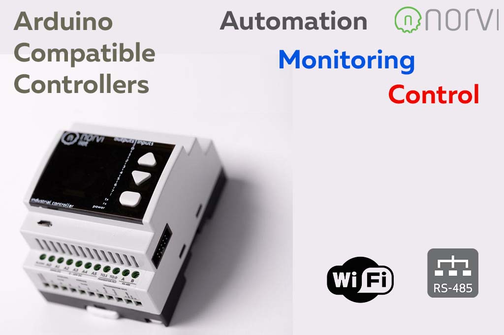
  1. Arduino Compatibility: NORVI IIOT is fully compatible with the Arduino ecosystem, allowing users to leverage the vast library of existing code, tutorials, and community support. This compatibility ensures a smooth transition for Arduino enthusiasts, enabling them to extend their knowledge and skills to industrial automation projects seamlessly.
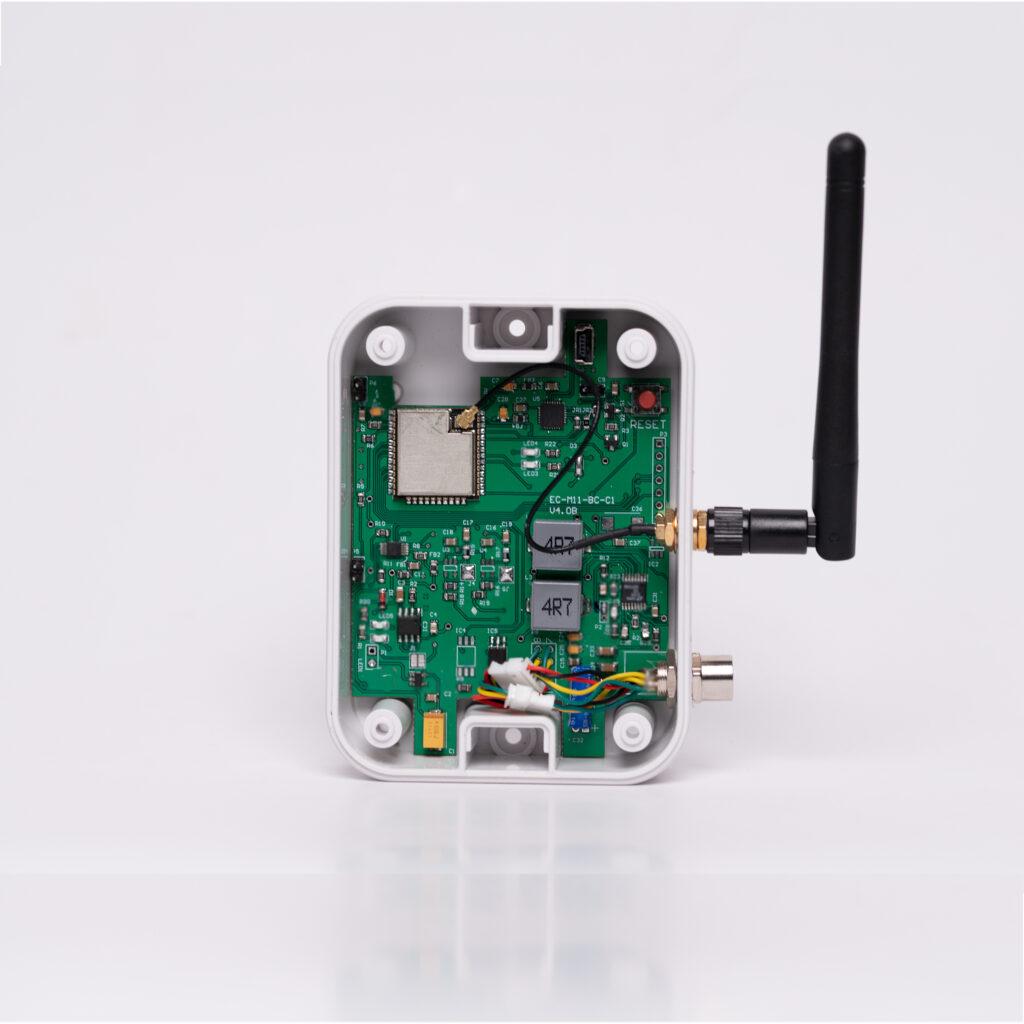
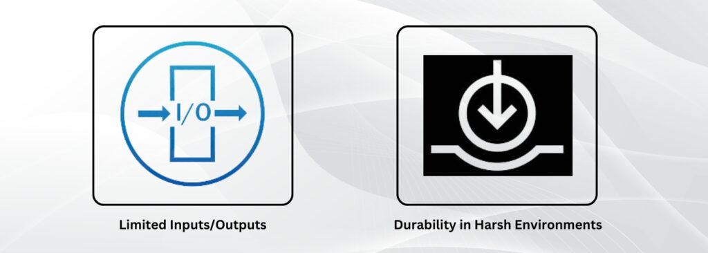
  2. Industrial-Grade Design: NORVI IIOT is designed to meet the demanding conditions of industrial environments. It incorporates rugged components and adheres to stringent quality standards, ensuring reliable operation in harsh conditions, temperature variations, and electromagnetic interference.
  3. Extensive I/O Options: NORVI IIOT offers a wide range of input and output options, including digital and analog ports, allowing for easy integration with sensors, actuators, and other industrial devices. This flexibility enables the monitoring and control of various processes, making it suitable for diverse applications across industries.
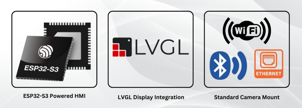
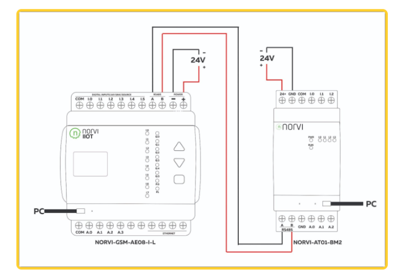
  4. Communication Protocols: NORVI IIOT supports popular communication protocols such as Modbus, MQTT, and Ethernet/IP, enabling seamless integration with existing industrial networks and protocols. This capability facilitates real-time data exchange, remote monitoring, and integration with supervisory control and data acquisition (SCADA) systems.
  5. Edge Computing and Analytics: NORVI IIOT is equipped with powerful computational capabilities, enabling edge computing and data analysis at the source. This eliminates the need for transmitting large volumes of data to a central server, enabling real-time decision-making, predictive maintenance, and optimization of industrial processes.
  6. Scalability and Flexibility: NORVI IIOT is designed to be scalable, allowing users to expand its capabilities by adding additional I/O modules as per project requirements. This scalability ensures future-proofing and adaptability to evolving automation needs, making it a cost-effective choice for both small-scale and large-scale applications.

Applications of NORVI IIOT

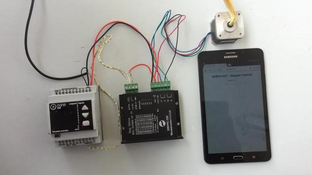
  1. Industrial Automation: NORVI IIOT can be employed in various industrial automation scenarios, including machine control, production line monitoring, and data acquisition. Its Arduino compatibility makes it a versatile solution for rapid prototyping and implementing automation projects across different industries.
  2. Smart Buildings: NORVI IIOT enables intelligent control and monitoring of building systems such as lighting, HVAC, access control, and energy management. Its compatibility with Arduino allows for customization and integration with smart home automation systems, enhancing energy efficiency and occupant comfort. 
  3. Environmental Monitoring: NORVI IIOT can be utilized for environmental monitoring applications, including air quality sensing, water quality monitoring, and weather stations. Its compatibility with Arduino simplifies the development of monitoring solutions for sustainable resource management and environmental conservation.
  4. Research and Education: NORVI IIOT’s Arduino compatibility makes it an excellent platform for educational institutions and research labs. It allows students, educators, and researchers to explore and experiment with industrial automation concepts, enhancing their understanding and practical skills.

    NORVI IIOT’s compatibility with Arduino offers a powerful combination of simplicity and versatility for industrial automation. By embracing Arduino’s extensive ecosystem, NORVI

    Industrial IoT Device
    Programmable IoT Device

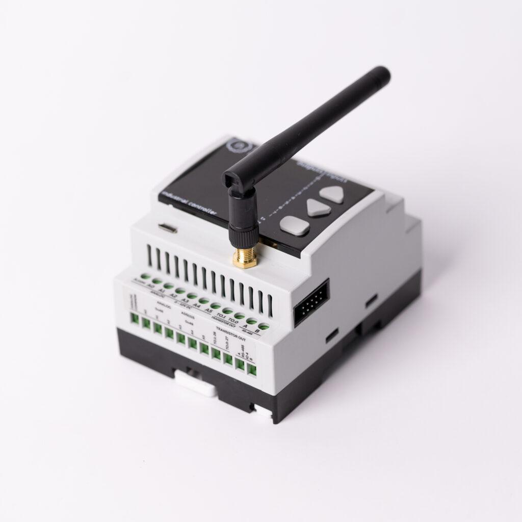
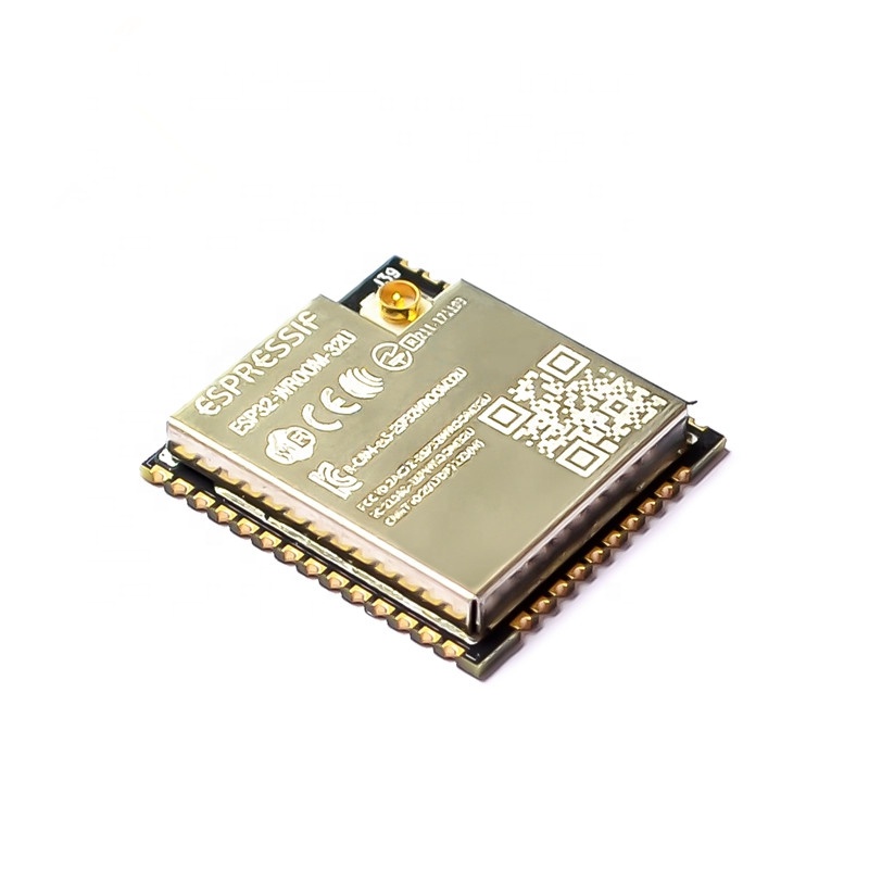
    The NORVI IIOT, powered by the cutting-edge ESP32-WROOM32 chip is now available for purchase!

    Elevate your PLC and IoT experience and explore the limitless possibilities of innovative technology. Get yours today and step into the future of industrial IoT.

    Visit our PRODUCT PAGE or, Contact Us at [email protected]

    Stay Connected to get updated news on LVGL for HMI: Facebook : LinkedIn : Twitter: YouTube

    Posted on

    Expanding I/O Capabilities of NORVI Series

    I/O (input/output) is a critical part of any programmable logic controller (PLC) system. It allows for the efficient and reliable connection of external devices to the PLC, allowing for more complex control systems.

    NORVI ESP32 Industrial Arduino, has served with the best I/O combinations for both monitoring and controlling applications. On the base unit, NORVI Controllers offer below I/O Capabilities. 

    • Digital Inputs
    • 4-20mA Analog Inputs
    • 0 – 10V Analog Inputs
    • Transistor Outputs 
    • Relay Outputs

    We are planning to discuss the capabilities of the Digital Inputs , Transistor outputs in a separate document. Including how they can be utilized for industrial applications. 

    While we discover more and more use of the NORVI Industrial Controllers we added the expandability of I/O Capabilities.

    The most obvious advantage of using I/O expansion in an Arduino PLC system is the ability to connect more external devices and increase the capacity of the system. With the use of I/O expansion, the number of devices that can be connected to the Arduino PLC can be increased significantly. This provides the user with greater flexibility, allowing them to control more devices with a single PLC. 

    Another advantage of I/O expansion is the improvement of system reliability. By connecting more external devices to the PLC, the system can be monitored and controlled more accurately. This ensures that any errors or malfunctions in the system are detected quickly and efficiently. In addition, I/O expansion can help to reduce the cost of a PLC system. By adding more I/O expansion, the total cost of the system can be reduced. This is because the cost of the additional I/O expansion is much lower than the cost

    We have launched below expansion products; 

    1. Analog Input Expansions
    2. Digital Input Expansions
    3. Transistor Output Expansions
    4. Relay Output Expansions

    In the near future, we will be launching the LoRaWAN expansion module to enable users to get the best out of NORVI Controllers. 

    Posted on

    ESP32 based Industrial Controllers

    M11 E Series

    What is ESP32 and Why ESP32 for IoT applications?

    The ESP32 is a low-power system on a chip (SoC) series, created by Espressif Systems. The features and the specifications of this chip have made itself established as the go-to chip or module in the IoT world. With different chip models available in the market, its capabilities and resources  have grown impressively over the past years.

    ESP32 is rapidly becoming a popular choice for IoT applications due to its economical prices, multiple component support design, built-in Wi-Fi & Bluetooth, and easy compatibility with Arduino and many other boards.

    NORVI Controllers – bridging the gap between existing features of ESP32 and supporting Industrial applications

    Even though ESP32 has great specifications for ordinary IoT applications, to use them in Industrial IoT applications, certain factors such as proper enclosure, good power supply, I/O isolations and EMI Safety have to be considered. Having realised this, NORVI Controllers is producing ESP32 based controllers for industrial automation and IoT solutions, bridging the gap between the existing features of the ESP32 and supporting industrial applications.

    Features of ESP32 based NORVI CONTROLLERS

    • Variety of models for different industrial applications 
    1. Relay models
    2. 4-20 mA current sensor models
    3. 0-10V voltage sensor models and more
    • Extended Connectivity options apart from WIFI and Bluetooth
    1. RS-485, Modbus via RS485
    2. NB-IOT
    3. LORA
    4. Ethernet
    • Built-in Display and push buttons for user friendly experience.
    • Supports Arduino IDE, ESP-IDF and more for programming. Tutorials and guide for getting started with the devices.
    • Low cost devices when compared with the PLC controllers which do the same job.

     For more information and support  reach us at – https://norvi.lk/contact-us/

    Posted on

    Customized Product Development

    CNC milling

    Product customization is important for effectively servicing your customer base. Customers don’t all want the same thing or use the product in the same manner. Product customization is critical for providing a personalized consumer experience to each user group, and it can boost customer engagement and satisfaction. Having realized this, we offer customized services in the domain of Embedded Systems on PCB designing, manufacturing, assembly, machining & printing.

    Why NORVI for Product Development?

    • We use top-of-the-line PCB modeling software. This ensures that we produce projects that are not only industry standard, but also simple to maintain.
    • We have ready-to-use products from which you can begin developing your design while a device is custom-made for you. Our design services have a high performance record, and we follow all well-known design standards to guarantee that there are no errors, allowing the products to reach the market sooner.
    • We believe in doing it well the first time and before the product is sent to you, NORVI employs extensive procedures to ensure that any entrapped defects are corrected. As a result, you’ll save time, money, and a tedious period of inaccurate outputs and alterations to fix them.
    • Our process has been fine-tuned for the quickest time to market. The ability to manufacture and assemble products in-house allows for greater control and speed in the production process.
    • Keeping our IoT product creation process onshore ensures hassle-free intellectual property and security, as well as the benefits of versatility and speed.
    • We guarantee perfect fit and finish, whether it’s a prototype or a production unit. We can print and cut the ideal finish for your product without limiting output volume as we have both printing and milling capabilities in-house.
    • We are dedicated to providing you with the professional assistance you need to ensure the completion of your project. 

    For more information and support : https://norvi.lk/contact-

    Posted on

    Programmable devices for IoT

    Why NORVI Programmable IoT Devices
    – Cut build time and consolidate the process,
    – Pre- certified products
    – Ability to customize I/O requirements.
    – Example programs for variety of applications.

    Applications :
    – MQTT End device
    – Modbus sensor node
    – Machine / Equipment monitoring system

    Checkout our product range on https://norvi.lk/products/

    The introduction of micro controller-based boards has sparked a surge in interest in embedded systems, allowing a large number of people to show interest in the field of micro-controllers and IoT. This has increased the scope and applications in which they are used. The advent of easy to use micro-controller boards have increased the scope within which micro controllers are being used, especially paving a path to replace the PLCs in complex control systems.

    NORVI Industrial controllers are such programmable IoT devices based on micro-controllers. Unlike the usual controllers, these devices are designed with ruggedness and the ability to withstand extreme conditions, which makes them ready for industrial applications. Also they are designed according to the IEC standard which is usually at a range of current/voltage and interfaces for industrial applications.

    Programming these devices are simplified by providing the facility to code these devices using simplified platforms like Arduino IDE, with step by step guides available to the users.These ESP32 based devices come equipped with digital and analog I/O, enabling them to detect digital logic states and analog inputs, depending on the choice of the model. Variety of models in the Norvi lineup are capable of measuring the environmental factors like flow rate, pressure, temperature and offer analog inputs (for dedicated voltage/current measurement) at the industrial level. 

    Setting up the Norvi devices only require lesser wiring, which offers more flexibility to management of the device. And mainly, it is to be noted that the cost of the Norvi devices is kept in a much affordable range when compared to that of PLC devices, which do the same task in an industrial environment.

    Posted on

    Programmable MQTT Devices – NORVI

    Programmable MQTT Devices - NORVI

    The Industrial Internet of Things is a network of sensors and other devices that communicate with industrial systems, all in an effort to enhance the business operations. Manufacturing, agribusiness and oil & gas to name a few, all use a large range of sensors.These sensors transmit essential telemetry data to analytics engines, which search the data for patterns and irregularities, allowing businesses to better understand and optimize their operations.

    To transfer data from a field sensor to a field controller, to a site network, to a PC data server, and then to the cloud, conventional automation products and protocols usually require a rigorous configuration and hierarchy. These types of implementations can be difficult to develop and maintain. MQTT, which includes multiple functions to satisfy the needs of IIoT, has risen to popularity as a protocol for solving this issue. MQTT is a light and energy-efficient communication protocol with a fast response time.It makes the interaction between devices efficient, regardless of the number of devices involved.It guarantees fast data delivery with low latency all while reducing CPU and RAM load.

    Imagine a cloud-controlled device to measure the humidity in a farm, remotely. In the case of HTTP protocol, the device would have to continuously make GET requests to see if there’s a change in a variable, say Humidity Variable, and then take an action depending on the last reading. This necessitates a huge number of requests, and it isn’t entirely real-time because it is dependent on the polling frequency.MQTT allows the user to listen to the cloud and receive notifications only when a variable changes. The communication between the computer and the cloud is kept open in this manner, but data only moves when it is needed, saving battery life and network bandwidth while enhancing real-time performance.

    So it is clear that MQTT-capable industrial automation devices are the latest approach for combining commercial and industrial automation with the cloud using IIoT principles in a cost-effective, safe, and reliable manner.

    Norvi IoT devices are such industrial controllers that support MQTT protocol.These programmable MQTT devices come with a variety of features that make them suitable for industrial automation and IoT solutions. These devices come equipped with digital and analog I/O, enabling them to detect digital logic states and analog inputs, depending on the choice of the model.

    After selecting a programmable MQTT Iot device like Norvi, only simple legwork has to be done by the users to establish the MQTT connection. Refer this detailed article on connecting the Norvi device to the IoT cloud platform Ubidots over MQTT protocol with step by step instructions.Moreover, setting up the Norvi devices only requires lesser wiring, which offers more flexibility to management of the device.

    Connecting the Norvi device to the IoT cloud platform Ubidots over MQTT protocol Article

    To check the Norvi device line up www.norvi.lk

    Posted on

    Modbus RTU Communication Through ESP32 NORVI Devices

    This guide will explore how Modbus RTU communicates through ESP32 using NORVI Controllers, enabling efficient data transmission and remote monitoring or control capabilities. A detailed guide can be referred to below.

    In modern IoT applications, communication protocols play a vital role in exchanging data between devices and systems. 

    Modbus is a widely used protocol in industrial automation, which is an efficient protocol for IoT messaging. 

    Setting up NORVI ESP32 devices as MODBUS master and slave is a powerful way to enhance your industrial IoT solutions. 

    This setup will allow the master device to read digital and analog inputs from the slave device, enabling efficient data acquisition and management in your industrial applications.

    Modbus RTU Communication Through NORVI

    We’ll be using two NORVI ESP32 devices: one as a master and one as a slave. 

    The NORVI-GSM-AE08-I-L will act as the master, while the NORVI-AT01-BM2 will be the slave. 

    The master device (NORVI-GSM-AE08-I-L) will read the digital and analog inputs from the slave device (NORVI-AT01-BM2) and store the values.

    Requirements to get started

    • Two NORVI devices, one as a master and one as a slave.
    • Wires for connection
    • USB cable (Type A to Type B mini) for NORVI-AT01-BM2.
    • USB cable (Type A to Type B micro) for NORVI-GSM-AE08-I-L.

    Circuit Connection

    Basic Steps

    1. Compile and Upload the Test Program
    • Use NORVI-GSM-AE08-I-L as Master
    • Use NORVI-AT01-BM2 as Slave
    1. Upload Programs
    1. Download Test Programs
    • Download test programs here.
    1. Check Pin Configuration
    • Verify pin configuration in the programs.
    1. Run Programs Separately
    2. MODBUS Communication Results
    • COM33: NORVI-GSM-AE08-I-L Serial window
    • COM22: NORVI-AT01-BM2 Serial window
    1. Initial State
    • NORVI-GSM-AE08-I-L reads and prints digital input status of NORVI-AT01-BM2.
    • NORVI-GSM-AE08-I-L reads and prints analog input status of NORVI-AT01-BM2.

    Troubleshooting

    1. RS485 Check
    • Set FC pin high and low to test RS485.
    • Download RS485 example program here.
    • Verify pin configuration.
    1. RS485 Code Setup
    • Define FC, RXD, and TXD pins.
    • Initialize hardware and software serial ports.
    • Set FC pin as output.
    1. Loop Function
    • Transmit data by setting FC pin HIGH.
    • Send “RS485 01 SUCCESS” message.
    • Set FC pin LOW for receiving data.
    • Read and print data from RS485

    Sharing RX and TX with USB

    1. NORVI Devices,  RS485 Communication
    • Shared TX and RX pins for USB and RS485
    • Use an OLED display for data feedback when using these devices.

    NORVI as MODBUS Master

    1. Setup Master Device
    • Use NORVI-IIOT-AE02.
    • Add libraries: Modbus-esp8266, Adafruit GFX, Adafruit SSD1306.
    • Define screen width, height, reset pin, MODBUS slave ID, and registers.
    1. Setup and Loop Functions
    • Initialize serial communication, MODBUS RTU, I2C, and display.
    • Read holding registers from the slave.
    • Display readings on an OLED screen.

    NORVI as MODBUS Slave

    1. Setup Slave Device
    • Use NORVI-IIOT-AE02.
    • Add libraries: Modbus-esp8266, Adafruit GFX, Adafruit SSD1306.
    • Define screen width, height, reset pin, MODBUS slave ID, and inputs.
    1. Setup and Loop Functions
    • Initialize serial communication, MODBUS RTU, I2C, and display.
    • Read discrete input coils from the slave.
    • Display readings on OLED screen.

    Conclusion

    By following these steps, you can successfully set up and utilize NORVI ESP32 devices as MODBUS master and slave. This setup allows for reliable communication and data transfer in industrial applications, enhancing the functionality of your IoT controllers.

    • For a detailed guide and step-by-step instructions, please refer to our comprehensive guide here.
    • Watch our video tutorial for a visual walkthrough: Watch Video Tutorial.
    • Visit Our product page to buy products: Here.

    Enhance your industrial IoT solutions with NORVI’s reliable and expandable technology!

    Posted on

    Industrial Application of NORVI M12-C Series: Remote Environmental Monitoring

    The NORVI M12-C Series battery-powered IoT node is an ideal solution for remote environmental monitoring in locations without grid power. Designed for standalone installations, it leverages the STM32L1 microcontroller. It supports various low-power communication options such as GSM/LTE, NB-IoT, LoRa, and Zigbee 3.0, ensuring efficient data transmission while maximizing battery life.

    Scenario

    In a remote forest area, an environmental research team must monitor various environmental parameters such as temperature, humidity, and soil moisture. The absence of grid power poses a significant challenge.

    Solution

    Deployment: The NORVI M12-C Series devices are deployed at multiple monitoring points across the forest.

    Power Supply: Each device is powered by four inbuilt AA batteries, which also provide up to 12V output to power external sensors.

    Sensors: Various environmental sensors are connected to the devices, using flexible I/O combinations to measure temperature, humidity, and soil moisture levels.

    Data Transmission: Using the supported low-power communication options (e.g., LoRa for long-range communication), the devices transmit collected data to a central server for analysis. The communication method is chosen based on the specific needs and range requirements of the deployment area.

    Durability: The IP67-rated enclosure ensures that the devices can withstand harsh outdoor conditions, including rain, dust, and extreme temperatures.

    Benefits

    Energy Efficiency: Low-power communication options and efficient power management extend battery life, reducing the need for frequent maintenance.

    Reliable Data Collection: Continuous and reliable data collection from remote locations aids in comprehensive environmental monitoring and research.

    Scalability: The solution can be easily scaled by adding more devices to cover larger areas or monitor additional parameters.

    Cost-Effective: Eliminates the need for extensive infrastructure setup and grid power, making it a cost-effective solution for remote monitoring applications.

    This application showcases the versatility and robustness of the NORVI M12-C Series in addressing the challenges of remote environmental monitoring, providing a reliable and efficient solution for data collection in off-grid locations.

    Posted on

    Industrial Grid-Powered Monitoring with NORVI SSN M11-E Series

    With the advancement of Industry 4.0, the demand for robust, real-time monitoring systems in industrial environments has surged. The NORVI SSN M11-E series, using the ESP32-WROOM32 System on Chip (SoC), presents a potent solution for such applications. This series offers flexible Input/Output (I/O) configurations, a wide input voltage range, and robust communication capabilities, making it ideal for a broad spectrum of industrial monitoring tasks such as Industrial Grid-Powered Monitoring.

    Key Features

    M11 E Series

    Versatile I/O Configurations

    The M11-E series comprises several models, each tailored to specific sensor inputs and communication requirements:

    • EC-M11-EG-C1: 2 Digital Inputs, 2 Analog Inputs (0 – 10V DC), 1 RS-485 Communication
    • EC-M11-EG-C2: 2 Digital Inputs, 1 RS-485 Communication
    • EC-M11-EG-C3: 1 Load Cell Input
    • EC-M11-EG-C4: 1 Thermocouple Input
    • EC-M11-EG-C5: 1 I2C Communication, 1 3.3V/5V DC Output

    Robust Communication

    The series supports expansions for GSM/LTE, NB-IoT, and LoRa, ensuring reliable data transmission in diverse environments. Additionally, the RS-485 communication port enables stable, long-distance data transfer within industrial settings.

    Wide Input Voltage Range

    Operating within a 9 – 36V DC range, the M11-E series can be seamlessly integrated into existing industrial power infrastructures, offering flexibility and ease of deployment.

    Industrial Design

    Encased in an IP67-rated enclosure, the M11-E series is engineered to withstand harsh industrial conditions, including exposure to dust and water. This ensures durability and reliability in demanding environments.

    Application Implementation

    Initialization

    The initial phase of deploying an industrial monitoring application with the M11-E series involves the setup of GPIO (General-Purpose Input/Output), ADC (Analog-to-Digital Converter), and communication interfaces such as RS-485. 

    Proper initialization ensures accurate data acquisition and reliable communication.

    Sensor Data Acquisition

    The device periodically samples data from connected sensors. 

    Digital inputs monitor binary states (e.g., on/off conditions), while analog inputs measure varying signals, providing detailed information about environmental parameters. 

    Specific models also support data acquisition from load cells, thermocouples, or I2C sensors, tailored to the application requirements.

    Data Processing

    Once collected, the data undergoes processing and formatting for transmission. 

    This step includes filtering noise, scaling sensor readings, and converting raw data into actionable metrics. 

    Proper data processing ensures that the transmitted data is precise and useful for subsequent analysis.

    Data Logging

    To enhance system reliability, M11-E series devices can log data locally. 

    This is crucial for scenarios where communication with the remote server is intermittent. 

    Local data storage ensures no data loss and facilitates data transmission once communication is restored.

    Communication

    The processed data is transmitted to a remote server using the chosen communication protocol. 

    RS-485 offers a stable wired connection for long-distance data transfer, while GSM/LTE and LoRa provide wireless options suitable for different industrial environments. 

    Ensuring robust communication is essential for real-time monitoring and timely decision-making.

    Error Handling

    Effective error handling is vital in industrial applications. 

    The system must detect and manage communication failures, power issues, and sensor malfunctions. 

    Implementing retry mechanisms, fallbacks, and alerts ensures the system remains operational and reliable.

    Power Management

    M11-E series devices are designed to operate efficiently within a wide input voltage range. 

    Monitoring the power supply and managing power consumption is critical to prevent downtime and ensure continuous operation in industrial settings.

    Conclusion

    The NORVI SSN M11-E series offers a comprehensive solution for industrial grid-powered monitoring applications. Its versatile I/O configurations, robust communication capabilities, and industrial design make it suitable for various industrial environments. Leveraging the ESP32-WROOM32 SoC, these devices provide flexibility, performance, and reliability, essential for modern industrial monitoring needs. Whether monitoring sensor values or parameters from external devices, the M11-E series stands out as a dependable choice for industrial IoT applications.

    ESP32 PLC


    Visit NORVI M11-E Series Page Now; Here

    Or, Contact our Technical support team for all of your technical problems at [email protected]

    Posted on

    RPI HMI Node-RED Introduction: Controlling Analog Inputs

    Example of RPI HMI NODE-RED integration is described in this article. NORVI has a set of node-red nodes that makes programming easy.

    Here is an example of using the Raspberry PI HMI Analog Input node for Node-RED. This node facilitates the control of NORVI-RPI-HMI analog inputs.

    The Raspberry HMI supports Node-Red programs. 

    HMI – ADC

    RPI HMI Node-RED

    The Analog Input Separation Node is designed to manage and process analog input signals efficiently. It’s particularly useful for working with sensors or devices that generate continuous analog signals, such as temperature sensors, light sensors, or pressure sensors.

    Inputs: Input HMI Analog Node

    Outputs: Integer or Double Analog Value of Selected Channel

    Configuration

    Channel: Channel Number

    Users can configure the node to handle specific analog inputs by selecting the appropriate settings within the node’s properties

    Analog Value: Raw ADC Value

    Output Value: Value Mapped for Raw ADC value specified in Raw ADC Value

    Decimal Point: Number of decimal points to round off (Max. 3)

    Users can enter the analog value and the output values to this node.

    HMI-ANALOG

    The Analog Read Node is used to initialize the analog module and read analog channels. When integrated with Analog Input Separation Nodes, it facilitates the independent monitoring and analysis of distinct analog input signals. This synergy enables users to precisely observe and evaluate individual values, contributing to a comprehensive understanding of the analog input data within the Node-RED environment.

    Inputs: Input TRUE once to initialize, the Boolean

    Outputs: All 8 channels are available as msg.AN0 – msg.AN7.

    To extract the output for individual channels use HMI ADC Node

    Example Program - RPI HMI NODE-RED integration

    Let’s create a simple example program using the RPI-HMI-ADC node and RPI-HMI-ANALOG node. When an input is provided, the dashboard will show the corresponding analog input value.

    Here, to display the program in the Node-RED dashboard, added a test node (CH5 & CH6) as a dashboard node.

    After configuring the program, the user interface of the RPI HMI should look like this,

    Analog Input 5 is active, but Analog Input 6 is inactive.

    Analog Input 6 is active, but Analog Input 5 is inactive.

    Hope readers got a clear understanding about how to use RPI HMI Node-RED integration for Controlling Analog Inputs.

    Posted on

    Raspberry Pi HMI Node-RED Introduction: Controlling Digital Inputs

    Example of  Raspberry Pi HMI Node-RED. NORVI has a set of node-red nodes that makes programming easy. 

    Here is an example of using the Raspberry PI HMI Digital Input node for Node-RED. This node facilitates the control of NORVI-RPI-HMI inputs.

    The Raspberry HMI supports Node-Red programs. 

    HMI-I1 Node :

    The HMI-I1 node serves as a digital input node, representing the inputs of the HMI. It generates a “msg. payload” with either a 0 or 1 depending on the state of the input pin. Configuration of this node involves selecting the desired input.

    Inputs: msg. payload (Boolean) – The payload will be a TRUE or a FALSE.

    Outputs: msg. payload (Boolean) – The payload will be a TRUE or a FALSE.

    TRIGGER TYPE: RISING, FALLING, BOTH

    INPUT = SELECT INPUT NUMBER

    Lorem ipsum dolor sit amet, consectetur adipiscing elit. Ut elit tellus, luctus nec ullamcorper mattis, pulvinar dapibus leo.

    Example Program: Raspberry Pi HMI Node-RED - Controlling Digital Inputs

    Let’s create a simple example program using the RPI-HMI-IN node. When a button is pressed it contains true and false and this represents a trigger. Here, to display the program in the Node-RED dashboard added a switch node (digi 01 & digi 02) to it as a dashboard node.

    After setting the configuration of the program, the user interface of the RPI HMI should be as below.

    • Digital Input 1 ON and Digital Input 2 OFF 
    • Digital Input 1 OFF and Digital Input 2 ON

    This schematic shows the connection between the RPI-HMI inputs. When the inputs are in the OFF state, the GPIO goes LOW, and when the input is in the ON state, the GPIO goes HIGH.

    Posted on

    Node-Red on RPI HMI Introduction: Controlling Transistor Outputs

    Example of Node-Red on RPI HMI applications. NORVI has a set of node-red nodes that makes programming easy.


    Here is an example of using the Raspberry PI HMI Transistor Outputs ON and OFF node for Node-RED. This node facilitates the control of NORVI-RPI-HMI outputs. Check out How Node-Red on RPI HMI works.

    The Raspberry HMI supports Node-Red programs.I

    HMI-Q1 Node

    The HMI-Q1 node serves as a digital output node. It accepts a “msg. payload” with either a 0 or 1, setting the selected physical pin high or low based on the passed value. 

    Inputs: payload number | string | Boolean
    When sending a message to the Node-RED HMI-Q1 node, use any of these inputs to control the output. For example, sending Boolean true turns the output on, and sending Boolean false turns it off. Similarly, sending either the number 1 or the string “ON” can turn the output on, depending on how the flow is configured.

    Output = Desired output can be selected in node configuration.

    Example of Node-Red on RPI HMI

    Let’s create a simple example program using the RPI-HMI-OUT node. When a button is pressed, it contains true and false values, representing a trigger. Display the program on the Node-RED dashboard by adding a switch node (Q7 ON & Q7 OFF) as a dashboard node.

    To display the program in the Node-RED dashboard add a button node (Toggle Switch7) to it as a dashboard node.

    After setting the configuration of the program, the user interface of the RPI HMI should be as below.

    • ON state – When the output is in the ON state, it means the output is activated, and the LED associated with it is illuminated.
    • OFF state – When the output is in the OFF state, it means the output is deactivated, and the LED associated with it is turned off.

    This schematic shows the connection between the RPI-HMI output and the LED. The RPI-HMI output is connected to the GND end of the LED, while the other end of the LED is connected to a resistor, and then to the power in(24+).

    Posted on Leave a comment

    ESP32 PLC PWM Outputs for Motor Speed Control : A Complete guide

    ESP32 PLC PWM Outputs

    In this article, we explore how to use ESP32 PLC PWM Outputs to regulate motor speeds efficiently using NORVI IIOT Device, equipped with an ESP32-WROOM32 module.

    With its built-in features like OLED display, digital and analog inputs, relay outputs, and DIN-rail mount, NORVI IIOT proves to be a versatile platform for motor control applications.

    Understanding PWM

    ESP32 PWM Outputs

    PWM stands for Pulse Width Modulation. It is a modulation technique used to encode a message into a pulsing signal. 

    In PWM, the digital signal is turned on and off at a certain frequency with varying pulse widths, or duty cycles. 

    The duty cycle refers to the percentage of time the signal is on (high) compared to the total period of the signal.

    PWM is commonly used in various applications, 

    • Motor control
    • Power regulation
    • Communication systems
    • LED dimming. 

    As an example, In motor control applications, PWM is used to control the speed of motors by varying the average voltage or current supplied to the motor. By adjusting the duty cycle of the PWM signal, the effective power delivered to the motor can be controlled, thus regulating its speed.

    PWM offers several advantages, 

    • Efficiency 
    • Simplicity
    • Flexibility (It allows for precise control over the average power delivered to a load, enabling smooth and accurate adjustments in motor speeds or other controlled systems.) 
    • Simple and cost-effective implementation

    ESP32 PWM Outputs

    ESP32 PWM Outputs

    The ESP32 microcontroller, which features a dual-core processor and Wi-Fi/Bluetooth connectivity, offers flexible PWM (Pulse Width Modulation) capabilities suitable for various applications.

    The ESP32 provides multiple PWM channels, allowing simultaneous control of multiple devices or components. Here’s an overview of the ESP32 PLC PWM Outputs:

    • Number of PWM Channels: It provides up to 16 PWM channels, which can be distributed across different GPIO (General Purpose Input/Output) pins.
    • PWM Frequency: The PWM frequency is configurable, allowing you to adjust it based on your application requirements. The frequency range typically spans from a few Hz to several kHz.
    • Resolution: The PWM resolution refers to the number of bits representing the duty cycle. The ESP32 supports adjustable PWM resolution, commonly ranging from 1 to 16 bits—higher resolution results in smoother and more precise control over the output signal.
    • Duty Cycle Control: The duty cycle of each PWM channel can be adjusted independently. The duty cycle represents the ratio of the signal’s on-time to its total period and is often expressed as a percentage.
    • Programming Interface: You can control the PWM outputs on the ESP32 using the ESP-IDF (Espressif IoT Development Framework), Arduino IDE with the ESP32 board package, or other compatible development environments. Libraries and APIs provided by Espressif Systems facilitate easy configuration and control of PWM channels.

    Utilizing NORVI IIOT for Motor Speed Control

    In the context of motor control, PWM is used to regulate the power supplied to the motor by controlling the average voltage and current through varying the duty cycle of the signal. A higher duty cycle translates to a higher average voltage and vice versa, thus controlling the speed of the motor. 

    Let’s look into the process of how ESP32 PLC PWM Outputs are used for controlling the Motor speeds.

    Hardware Setup:

      • Connect the motor to the PWM output pins (transistor outputs) of the NORVI IIOT device.
      • Ensure proper power supply and grounding for both the NORVI IIOT and the motor.
      • Utilize the built-in 0.96 OLED display for monitoring and feedback purposes. (If not NORVI ESP32 HMI can be connected for monitoring and feedback purposes)

    Software Implementation:

      • Initialize the PWM module on the NORVI IIOT using the provided libraries or SDK.
      • Configure the PWM output pins for motor control.
      • Implement a control algorithm to adjust the duty cycle based on desired speed inputs.
      • Utilize the digital and analog inputs for receiving speed commands or feedback signals.
      • Implement safety features such as overcurrent protection and emergency stop functionalities.

    User Interface and Interaction:

        • Utilize the built-in button on the front panel for manual control or mode selection.
        • Develop a user-friendly interface on the OLED display (or ESP32 HMI) for displaying motor speed, status, and other relevant information.
        • Enable remote monitoring and control capabilities through network connectivity options supported by NORVI IIOT.

    Expansion and Integration:

      • Take advantage of the expansion port to add additional functionalities or modules for enhanced motor control capabilities.
      • Integrate with other industrial automation systems or IoT platforms for seamless data exchange and interoperability.


    Benefits of Using NORVI IIOT for Motor Speed Control:

    • Compact and robust design suitable for industrial environments.
    • Versatile inputs and outputs for interfacing with various sensors, actuators, and peripherals.
    • Real-time monitoring and control capabilities.
    • Scalability and expandability for future requirements.
    • Cost-effective solution compared to traditional PLC-based systems.

    Conclusion

    By using the ESP32 PWM outputs of the NORVI IIOT device, associated with its advanced features and capabilities, system integrators, engineers and developers can effectively regulate motor speeds in industrial applications. Whether it’s for controlling conveyor belts, pumps, fans, or other motor-driven equipment, NORVI IIOT provides a reliable platform for achieving precise and efficient motor control, ultimately contributing to improved productivity and operational performance in industrial settings.

    If you have any questions, Please reach our technical team at [email protected]

    VISIT OUR Product Pages to get More Information: NORVI IIOT & NORVI ESP32 HMI

    Posted on

    Raspberry PI for Innovative Industrial Applications : 8 Applications You should Know

    The Raspberry Pi is a compact, cost-effective computer renowned for its versatility across various applications. As a single-board computer, it encapsulates a complete computing system within a diminutive form factor. Developed by the Raspberry Pi Foundation in 2012, its primary aim was to democratize access to computing and programming skills.

    Measuring merely as a circuit board, the Raspberry Pi integrates a Broadcom system-on-a-chip featuring a 700MHz ARM processor and graphics processor, complemented by 512MB of RAM. Its connectivity options include HDMI, Ethernet, USB ports, a 3.5mm audio jack, and a microSD card slot for storage. Operating on the Linux OS, it draws power from a 5V micro USB power supply.

    The utility of the Raspberry Pi spans a broad spectrum of tasks, ranging from rudimentary computing to intricate applications. It serves as a versatile platform, adaptable as a web server, media center, gaming console, or even a home automation hub. Moreover, it stands as an invaluable resource for burgeoning programmers, facilitating the learning of languages like Python, Scratch, and C/C++.

    In essence, the Raspberry Pi epitomizes accessibility and empowerment, empowering individuals to explore computing and programming in an affordable and user-friendly manner.

    How does Raspberry Pi Function?

    The Raspberry Pi exemplifies a single-board computer design, where all essential components are integrated into a solitary circuit board. Featuring a central processing unit (CPU), RAM, GPU, USB ports, and other vital elements, it embodies a comprehensive computing system in a compact form.

    Operating on diverse platforms like Linux or Windows, the Raspberry Pi is adept at fulfilling various computational needs, from multimedia playback to gaming. Its affordability and accessibility render it an ideal educational tool, enabling individuals from all backgrounds to engage with computing concepts effectively. Moreover, its versatility extends to a multitude of projects and applications, including Internet of Things (IoT) devices and media streaming solutions, facilitating experimentation with cutting-edge technologies at a nominal cost.

    Upon installing the operating system, the Raspberry Pi seamlessly interfaces with output devices such as computer monitors or HDMI televisions, while also accommodating input devices like mice or keyboards. This streamlined connectivity underscores its user-friendly design, enhancing its appeal across diverse user demographics.

    Raspberry PI CM4

    The Raspberry Pi Compute Module 4 stands out as a potent, budget-friendly, and compact embedded computing solution, catering to diverse application needs. Leveraging the prowess of the Raspberry Pi 4, it inherits a robust feature set, boasting 4K video output, dual monitor compatibility, up to 4GB of RAM, and Gigabit Ethernet support.

    Notably, the Compute Module 4 encompasses a broad array of I/O interfaces, encompassing USB, HDMI, GPIO, and camera connectivity. Its diminutive form factor renders it exceptionally suitable for scenarios demanding space-efficient solutions. Consequently, it finds resonance in industrial, medical, and automotive domains, where compactness is paramount.

    Moreover, the module’s adaptability shines through its high degree of customization, allowing tailoring to specific requirements. This versatility positions it as an attractive choice for innovators across various sectors, fostering creativity and innovation. Ultimately, the Raspberry Pi Compute Module 4 emerges as a versatile, cost-effective, and adaptable solution, poised to address the burgeoning demands of embedded applications.

    Raspberry Pi Industrial applications

    1. Raspberry Pi technology is increasingly being used in industrial applications due to its affordability, versatility, and small form factor. Here’s how Raspberry Pi technology is being utilized in industrial settings:
    2. Monitoring and Control Systems: Raspberry Pi boards can be used to monitor and control industrial processes such as temperature, humidity, pressure, and other environmental factors. They can interface with sensors and actuators through GPIO pins or using additional modules like ADC (Analog-to-Digital Converter) or DAC (Digital-to-Analog Converter) boards.
    3. Data Logging and Analysis: Raspberry Pi can collect data from various sensors and devices in real time and store it locally or transmit it to a centralized server for analysis. This data can be used for predictive maintenance, performance optimization, and quality control in industrial environments.
    4. Remote Monitoring and Management: Raspberry Pi devices can be deployed in remote locations to monitor equipment, machinery, and infrastructure. With network connectivity options like Ethernet, Wi-Fi, or cellular, they can transmit data to a central monitoring system and enable remote management and troubleshooting.
    5. Embedded Systems and HMI (Human-Machine Interface): Raspberry Pi can serve as a platform for building embedded systems and HMIs for industrial machinery and equipment. They can run custom software interfaces, control panels, and visualization dashboards to interact with operators and provide real-time feedback.
    6. Automation and Control Systems: Raspberry Pi can be integrated into automation and control systems to automate repetitive tasks, regulate processes, and improve efficiency in manufacturing, logistics, and other industrial sectors. They can run open-source automation software like Node-RED, OpenPLC, or CODESYS.
    7. Edge Computing: Raspberry Pi devices can perform edge computing tasks by processing data locally at the source instead of sending it to a centralized server. This reduces latency, bandwidth usage, and dependence on cloud services, making it suitable for real-time applications in industrial automation and control.
    8. Custom Solutions and Prototyping: Raspberry Pi’s flexibility and programmability make it an ideal platform for prototyping and developing custom solutions tailored to specific industrial needs. It allows engineers and developers to rapidly iterate, test, and deploy new ideas and applications in the field.
    RPI-based Industrial HMI


    NORVI offers a Raspberry Pi (RPI) based Industrial Controller which serves as PLC + HMI. Find out more about the Newly added RPI_HMI HERE, or You can contact us at [email protected] to get to know more RPI products that can be developed based on your requirements.

    Posted on

    Adding Touchscreen Functionality to ESP32-S3 HMI to enhance User Experience

    Adding Touchscreen Functionality to ESP32-S3 HMI
    Adding Touchscreen Functionality to ESP32-S3 HMI

    ESP32 NORVI HMI is a powerful HMI resistive touch screen with an 800*480 resolution LCD display. It uses the ESP32-S3-WROOM-1-N4R8 module as the main control processor, with a dual-core 32-bit microprocessor, integrated WiFi and Bluetooth wireless functions, a main frequency of up to 240MHz, providing powerful performance and versatile applications, suitable for IoT application devices and other scenes.

    The module includes a 5.0-inch LCD display and a driver board. The display screen uses resistive touch technology. It supports a development environment such as Arduino IDE and is compatible with the LVGL graphics library. This enables developers to customize their UI interfaces and create interesting projects quickly and easily, greatly shortening the development cycle.

    A 5-inch resistive touch display is a touchscreen technology with a layered structure, comprising a flexible top layer and a rigid bottom layer separated by insulating dots. When pressure is applied, these layers make contact at specific points, and touch input is detected by measuring changes in voltage. Some common features of the touch panel are,

    • Accuracy and Pressure Sensitivity: Resistive touchscreens provide accurate touch input by detecting the precise point of contact.
    • Cost-Effectiveness: Resistive touch panels are cost-effective to produce, making them a popular choice for budget-friendly displays.
    • Versatility and Compatibility: Compatible with various input methods, resistive touchscreens can be operated with any object that applies pressure.
    • Calibration Requirements: Periodic calibration may be necessary to maintain accurate touch response.

    To add the touch functionality to an ESP32-S3 HMI, it will need to use a combination of the ESP32-S3 microcontroller, a suitable Touch library, and the LVGL  graphics library. Below are the general steps to add these functionalities:


    1. Set Up Development Environment:

    Install Arduino IDE on PC.

    Integrate ESP32 board support in Arduino IDE.

    Install required libraries for ESP32, touch, and LVGL. 

    The Touch library may need to use a library that is compatible with the specific 5-inch resistive touch.


    1. Include Libraries in Arduino Sketch:

    Include the required libraries at the beginning of the Arduino sketch:


    #include <XPT2046_Touchscreen.h>

    #include <lvgl.h>


    1. Initialize Touch parameters:
    • Initialize the set points

    The touch screen set points are configured through an example code provided by a touch library. By executing the code and interacting with the four sides of the display, the corresponding values are displayed in the serial monitor. This process enables the determination of touchscreen set points based on the user’s input and observation of the serial output.


    #define TOUCH_MAP_X1 270

     #define TOUCH_MAP_X2 3800

     #define TOUCH_MAP_Y1 3600

     #define TOUCH_MAP_Y2 330


    • Variables touch_last_x and touch_last_y store the last touched coordinates.


    int touch_last_x = 0, touch_last_y = 0;

    #if defined(TOUCH_XPT2046)

    XPT2046_Touchscreen ts(TOUCH_XPT2046_CS, TOUCH_XPT2046_INT);


    • Touch Initialization Function.


    void touch_init() {

    #if defined(TOUCH_XPT2046)

      SPI.begin(TOUCH_XPT2046_SCK, TOUCH_XPT2046_MISO, TOUCH_XPT2046_MOSI, TOUCH_XPT2046_CS);

      ts.begin();

      ts.setRotation(TOUCH_XPT2046_ROTATION);


    • Check for Touch Signal.


    bool touch_has_signal() {

    #if defined(TOUCH_XPT2046)

      return ts.tirqTouched();


    • Check if Touched


    bool touch_touched() {

    #if defined(TOUCH_XPT2046)

      if (ts.touched())  {

        TS_Point p = ts.getPoint();


    • Check if Touch Released.


    bool touch_released(){

    if defined(TOUCH_XPT2046)

      return true;


    Example

    This touch code provides an abstraction layer for the touch library, allowing the user to easily understand. The code includes initialization, event handling, and functions to check if the screen is touched or released. 

    If buttonXMin, buttonXMax, buttonYMin, and buttonYMax represent the borders or boundaries of the region on the touch screen corresponding to the position of the button. let’s see how to configure a button, and set its action. 


    #include <XPT2046_Touchscreen.h>

    #define TOUCH_CS 10 // Example pin for touch CS

    XPT2046_Touchscreen ts(TOUCH_CS);

    #define BUTTON_PIN 7 // Example pin for the button

    void setup() {

      Serial.begin(9600);

      ts.begin();

      pinMode(BUTTON_PIN, INPUT);

    }

    void loop() {

      // Read touch input

      TS_Point p = ts.getPoint();


      // Check if the touch screen is touched

      if (p.z > MINPRESSURE && p.z < MAXPRESSURE) {

        // Process touch input (e.g., map coordinates, perform actions)

        int mappedX = map(p.x, TS_MINX, TS_MAXX, 0, 800); // Adjust based on display size

        int mappedY = map(p.y, TS_MINY, TS_MAXY, 0, 480); // Adjust based on display size

        Serial.print(“Touched at X: “);

        Serial.print(mappedX);

        Serial.print(“, Y: “);

        Serial.println(mappedY);


        // Check if the touch is in the region of the button

        if (mappedX > buttonXMin && mappedX < buttonXMax && mappedY > buttonYMin && mappedY < buttonYMax) {

          // Button is pressed, perform action

          Serial.println(“Button Pressed!”);

          // Add button action here

        }

      }

    }