The Analog Input Separation Node is designed to manage and process analog input signals efficiently. It’s particularly useful for working with sensors or devices that generate continuous analog signals, such as temperature sensors, light sensors, or pressure sensors.
Inputs: Input HMI Analog Node
Outputs: Integer or Double Analog Value of Selected Channel
Configuration
Channel: Channel Number
Users can configure the node to handle specific analog inputs by selecting the appropriate settings within the node’s properties
Analog Value: Raw ADC Value
Output Value: Value Mapped for Raw ADC value specified in Raw ADC Value
Decimal Point: Number of decimal points to round off (Max. 3)
Users can enter the analog value and the output values to this node.
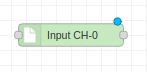
HMI-ANALOG
The Analog Read Node is used to initialize the analog module and read analog channels. When integrated with Analog Input Separation Nodes, it facilitates the independent monitoring and analysis of distinct analog input signals. This synergy enables users to precisely observe and evaluate individual values, contributing to a comprehensive understanding of the analog input data within the Node-RED environment.
Inputs: Input TRUE once to initialize, the Boolean
Outputs: All 8 channels are available as msg.AN0 – msg.AN7.
To extract the output for individual channels use HMI ADC Node
Example Program - RPI HMI NODE-RED integration
Let’s create a simple example program using the RPI-HMI-ADC node and RPI-HMI-ANALOG node. When an input is provided, the dashboard will show the corresponding analog input value.
Here, to display the program in the Node-RED dashboard, added a test node (CH5 & CH6) as a dashboard node.
After configuring the program, the user interface of the RPI HMI should look like this,
Analog Input 5 is active, but Analog Input 6 is inactive.
Analog Input 6 is active, but Analog Input 5 is inactive.
Hope readers got a clear understanding about how to use RPI HMI Node-RED integration for Controlling Analog Inputs.