This guide will explore how Modbus RTU communicates through ESP32 using NORVI Controllers, enabling efficient data transmission and remote monitoring or control capabilities. A detailed guide can be referred to below.

In modern IoT applications, communication protocols play a vital role in exchanging data between devices and systems. 

Modbus is a widely used protocol in industrial automation, which is an efficient protocol for IoT messaging. 

Setting up NORVI ESP32 devices as MODBUS master and slave is a powerful way to enhance your industrial IoT solutions. 

This setup will allow the master device to read digital and analog inputs from the slave device, enabling efficient data acquisition and management in your industrial applications.

Modbus RTU Communication Through NORVI

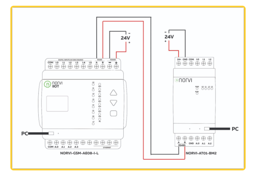
We’ll be using two NORVI ESP32 devices: one as a master and one as a slave. 

The NORVI-GSM-AE08-I-L will act as the master, while the NORVI-AT01-BM2 will be the slave. 

The master device (NORVI-GSM-AE08-I-L) will read the digital and analog inputs from the slave device (NORVI-AT01-BM2) and store the values.

Requirements to get started

  • Two NORVI devices, one as a master and one as a slave.
  • Wires for connection
  • USB cable (Type A to Type B mini) for NORVI-AT01-BM2.
  • USB cable (Type A to Type B micro) for NORVI-GSM-AE08-I-L.

Circuit Connection

Basic Steps

  1. Compile and Upload the Test Program
  • Use NORVI-GSM-AE08-I-L as Master
  • Use NORVI-AT01-BM2 as Slave
  1. Upload Programs
  1. Download Test Programs
  • Download test programs here.
  1. Check Pin Configuration
  • Verify pin configuration in the programs.
  1. Run Programs Separately
  2. MODBUS Communication Results
  • COM33: NORVI-GSM-AE08-I-L Serial window
  • COM22: NORVI-AT01-BM2 Serial window
  1. Initial State
  • NORVI-GSM-AE08-I-L reads and prints digital input status of NORVI-AT01-BM2.
  • NORVI-GSM-AE08-I-L reads and prints analog input status of NORVI-AT01-BM2.

Troubleshooting

  1. RS485 Check
  • Set FC pin high and low to test RS485.
  • Download RS485 example program here.
  • Verify pin configuration.
  1. RS485 Code Setup
  • Define FC, RXD, and TXD pins.
  • Initialize hardware and software serial ports.
  • Set FC pin as output.
  1. Loop Function
  • Transmit data by setting FC pin HIGH.
  • Send “RS485 01 SUCCESS” message.
  • Set FC pin LOW for receiving data.
  • Read and print data from RS485

Sharing RX and TX with USB

  1. NORVI Devices,  RS485 Communication
  • Shared TX and RX pins for USB and RS485
  • Use an OLED display for data feedback when using these devices.

NORVI as MODBUS Master

  1. Setup Master Device
  • Use NORVI-IIOT-AE02.
  • Add libraries: Modbus-esp8266, Adafruit GFX, Adafruit SSD1306.
  • Define screen width, height, reset pin, MODBUS slave ID, and registers.
  1. Setup and Loop Functions
  • Initialize serial communication, MODBUS RTU, I2C, and display.
  • Read holding registers from the slave.
  • Display readings on an OLED screen.

NORVI as MODBUS Slave

  1. Setup Slave Device
  • Use NORVI-IIOT-AE02.
  • Add libraries: Modbus-esp8266, Adafruit GFX, Adafruit SSD1306.
  • Define screen width, height, reset pin, MODBUS slave ID, and inputs.
  1. Setup and Loop Functions
  • Initialize serial communication, MODBUS RTU, I2C, and display.
  • Read discrete input coils from the slave.
  • Display readings on OLED screen.

Conclusion

By following these steps, you can successfully set up and utilize NORVI ESP32 devices as MODBUS master and slave. This setup allows for reliable communication and data transfer in industrial applications, enhancing the functionality of your IoT controllers.

  • For a detailed guide and step-by-step instructions, please refer to our comprehensive guide here.
  • Watch our video tutorial for a visual walkthrough: Watch Video Tutorial.
  • Visit Our product page to buy products: Here.

Enhance your industrial IoT solutions with NORVI’s reliable and expandable technology!