Connecting 4-20mA industrial sensors to an ESP32 PLC involves several steps, including understanding the sensor, configuring the ESP32, and handling the analog signal conversion. Here’s a comprehensive guide to help you:
Connect 4 - 20mA Industrial Sensors with ESP32 PLC
Connecting 4-20mA industrial sensors with an ESP32 PLC offers several advantages in industrial applications:
Compatibility: 4-20mA sensors are widely used in industrial settings due to their resilience against electrical interference and ability to transmit data over long distances without significant loss. ESP32 PLCs with analog input capabilities can easily interface with these sensors, enabling seamless integration into existing industrial systems.
Data Acquisition: ESP32 microcontrollers have analog-to-digital converters (ADCs) that can accurately read analog signals. By connecting 4-20mA sensors to the ESP32, you can efficiently capture and process sensor data, allowing for real-time monitoring and control of industrial processes.
Cost-effectiveness: ESP32 microcontrollers offer a cost-effective solution for acquiring sensor data. They provide flexibility, programmability, and connectivity options, making them suitable for various industrial automation and monitoring tasks at a relatively low cost compared to specialized PLCs.
Scalability and Customization: The ESP32 platform offers flexibility for customization and scalability. It allows developers to create tailored solutions by writing custom code to interpret sensor data, implement control algorithms, and interface with other devices or networks, meeting specific industrial requirements.
Internet Connectivity: ESP32 boards feature built-in Wi-Fi and Bluetooth capabilities, enabling connectivity to local networks or the internet. This connectivity facilitates remote monitoring, data logging, and control, offering enhanced accessibility and convenience in managing industrial processes.
Compact Size and Efficiency: ESP32 devices come in compact sizes, offering space-saving advantages in industrial environments. Despite their small form factor, they boast sufficient processing power and energy efficiency, suitable for continuous operation in industrial applications.
Understanding 4-20mA Industrial Sensors
Know Your Sensor: Identify the type of sensor you’re dealing with (temperature, pressure, etc.), its specifications, and the range of values it can output (typically 4-20mA).
Power Supply: 4-20mA sensors often require a power supply. They might operate on loop power, where the same two wires used for transmitting the signal also supply power to the sensor.
ESP32 PLC Setup
ESP32 Board Selection: Choose an ESP32 board suitable for PLC applications.
Analog Input: ESP32 boards usually have built-in ADCs (Analog to Digital Converters) that can read analog signals. Determine the number of analog input pins available and their specifications.
Signal Conditioning and Conversion
Current-to-Voltage Conversion: 4-20mA signals need to be converted to a voltage signal that the ADC can read. This involves using a resistor (known as a shunt resistor) to convert the current to a measurable voltage. Ohm’s law (V = IR) can be applied, where V is the voltage across the resistor, I is the current, and R is the resistor value.
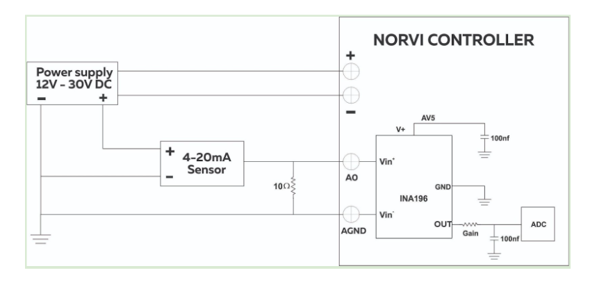
The INA196 measures the voltage drop across this shunt resistor. The voltage across the shunt resistor (Vshunt) can be calculated using Ohm’s Law:
Vshunt = Isensor × Rshunt
Vshunt is the voltage across the shunt resistor.
Isensor is the current through the sensor.
Rshunt is the resistance of the shunt resistor.
Once you have the voltage across the shunt resistor, you can use the gain equation for the INA196 to calculate the output voltage:
Vout =(Vshunt ×G)
Vout is the output voltage of the INA196.
G is the gain of the INA196.
Example:
Assuming a 4mA current sensor connected to the INA196, the sensor is likely producing a 4mA current through a shunt resistor, and
Isensor = 4mA
Rshunt = 10
Vshunt = Isensor × Rshunt
Vshunt = 4mA 10
Vshunt = 40mV
G(INA196) = 20 V/V
Vout =(Vshunt ×G)
Vout =(40mV ×20 V/V)
Vout = 0.8 V
Resistor Selection: Choose a suitable shunt resistor value to convert the 4-20mA range to a voltage range that doesn’t exceed the ESP32 ADC’s maximum input voltage.
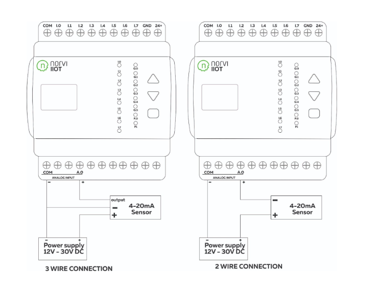
Circuit Connection
Connect the Sensor: Wire the sensor to the power supply and the shunt resistor. Ensure proper grounding and follow the sensor’s datasheet for correct wiring.
Connect to ESP32: Connect the output of the shunt resistor (voltage signal) to the ESP32’s analog input pin. Pay attention to the voltage range and make sure it falls within the ADC’s specifications.
ESP32 Programming
Analog Input Reading: Write code to read the analog voltage from the connected pin using the ADC library provided for the ESP32.
Voltage-to-Value Conversion: Convert the read voltage value to the actual sensor value using appropriate scaling formulas. Map the voltage range you’ve measured to the corresponding 4-20mA current range.
Testing and Calibration
Calibration: Test the setup with known values to calibrate and verify the accuracy of your sensor readings. Adjust scaling factors if needed.
Monitor Readings: Develop a monitoring system or interface (web-based, serial monitor, etc.) to display and log the sensor readings from the ESP32.
Considerations
Noise and Interference: 4-20mA signals are robust against noise, but ensure proper shielding and grounding to minimize interference.
Power Supply Stability: Ensure a stable power supply for both the sensor and the ESP32 to avoid fluctuations affecting sensor readings.
Safety Measures: Comply with safety standards and take necessary precautions, especially when dealing with industrial sensors and electrical components.
Conclusion
By following these steps and considering these aspects, you should be able to successfully interface 4-20mA industrial sensors with an ESP32-based PLC for accurate readings and monitoring in your industrial setup.
In summary, the process of linking 4-20mA industrial sensors to an ESP32 PLC is multifaceted. It involves comprehending the sensor’s operational requirements, configuring the ESP32 platform, and implementing signal conversion mechanisms. By utilizing a resistor to transform the sensor’s current output into a compatible voltage for the ESP32’s input, establishing secure and accurate connections, and developing code to interpret sensor data, a systematic approach ensures functionality. Rigorous testing, calibration with known benchmarks, and prioritizing safety measures contribute to the development of a robust and dependable system for collecting precise data from industrial sensors via an ESP32 PLC interface.
