Posted on Leave a comment

ESP32 PLC PWM Outputs for Motor Speed Control : A Complete guide

ESP32 PLC PWM Outputs

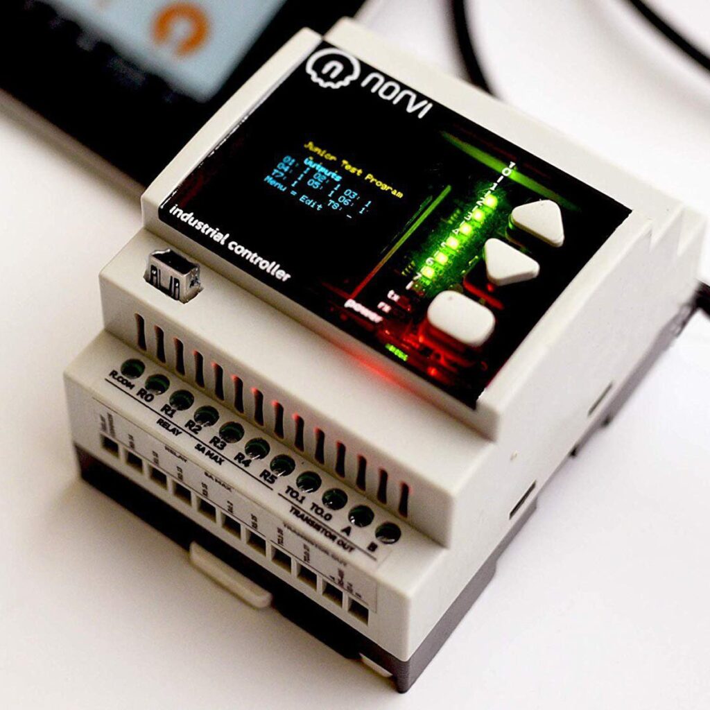
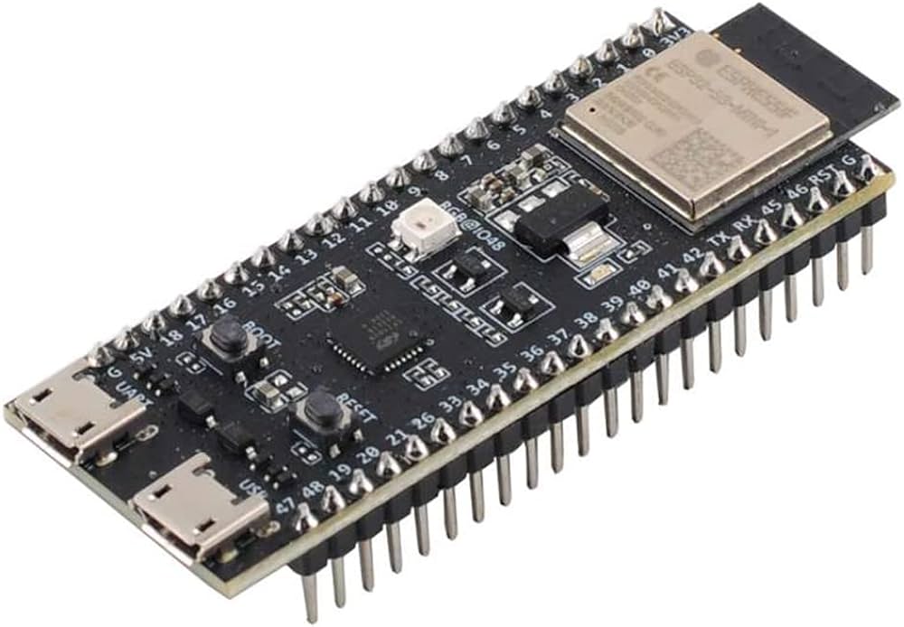
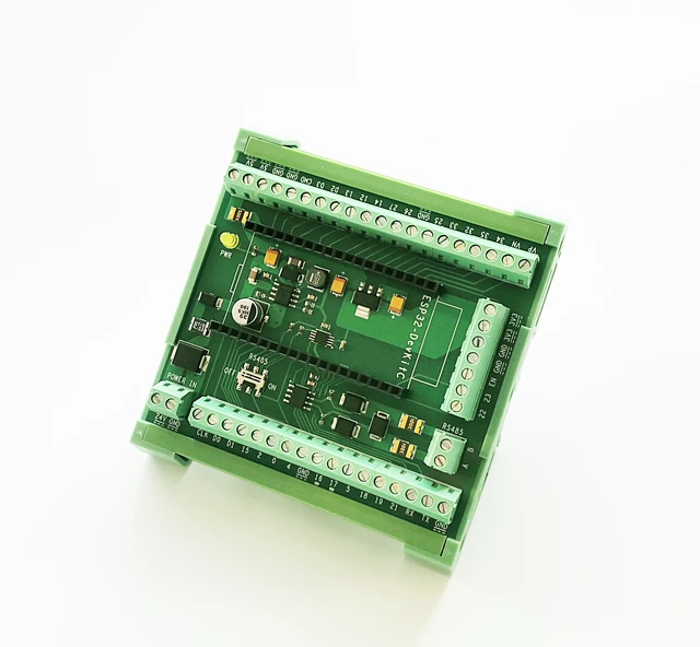
In this article, we explore how to use ESP32 PLC PWM Outputs to regulate motor speeds efficiently using NORVI IIOT Device, equipped with an ESP32-WROOM32 module.

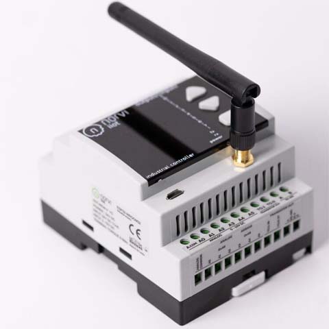
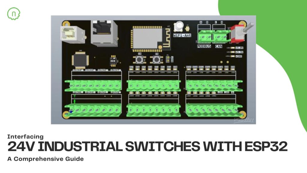
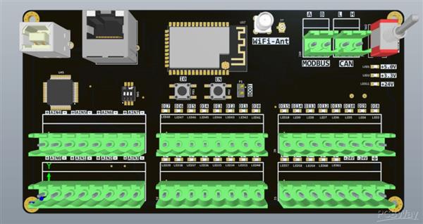
With its built-in features like OLED display, digital and analog inputs, relay outputs, and DIN-rail mount, NORVI IIOT proves to be a versatile platform for motor control applications.

Understanding PWM

ESP32 PWM Outputs

PWM stands for Pulse Width Modulation. It is a modulation technique used to encode a message into a pulsing signal. 

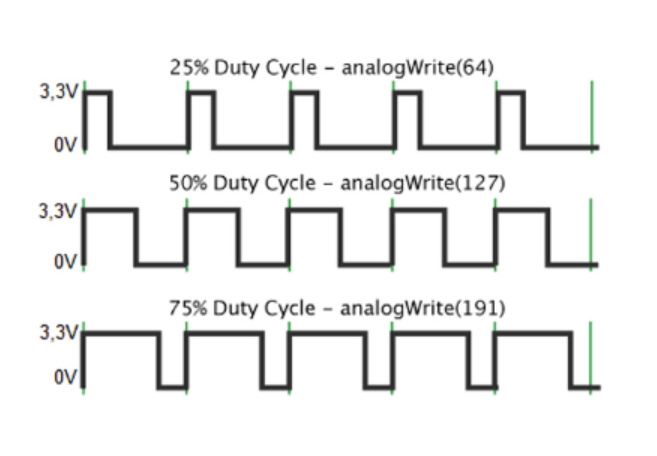
In PWM, the digital signal is turned on and off at a certain frequency with varying pulse widths, or duty cycles. 

The duty cycle refers to the percentage of time the signal is on (high) compared to the total period of the signal.

PWM is commonly used in various applications, 

  • Motor control
  • Power regulation
  • Communication systems
  • LED dimming. 

As an example, In motor control applications, PWM is used to control the speed of motors by varying the average voltage or current supplied to the motor. By adjusting the duty cycle of the PWM signal, the effective power delivered to the motor can be controlled, thus regulating its speed.

PWM offers several advantages, 

  • Efficiency 
  • Simplicity
  • Flexibility (It allows for precise control over the average power delivered to a load, enabling smooth and accurate adjustments in motor speeds or other controlled systems.) 
  • Simple and cost-effective implementation

ESP32 PWM Outputs

ESP32 PWM Outputs

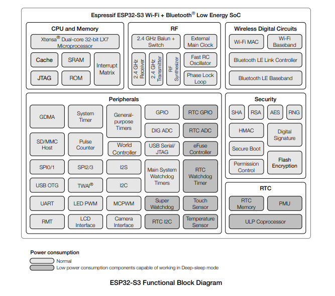
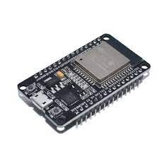
The ESP32 microcontroller, which features a dual-core processor and Wi-Fi/Bluetooth connectivity, offers flexible PWM (Pulse Width Modulation) capabilities suitable for various applications.

The ESP32 provides multiple PWM channels, allowing simultaneous control of multiple devices or components. Here’s an overview of the ESP32 PLC PWM Outputs:

  • Number of PWM Channels: It provides up to 16 PWM channels, which can be distributed across different GPIO (General Purpose Input/Output) pins.
  • PWM Frequency: The PWM frequency is configurable, allowing you to adjust it based on your application requirements. The frequency range typically spans from a few Hz to several kHz.
  • Resolution: The PWM resolution refers to the number of bits representing the duty cycle. The ESP32 supports adjustable PWM resolution, commonly ranging from 1 to 16 bits—higher resolution results in smoother and more precise control over the output signal.
  • Duty Cycle Control: The duty cycle of each PWM channel can be adjusted independently. The duty cycle represents the ratio of the signal’s on-time to its total period and is often expressed as a percentage.
  • Programming Interface: You can control the PWM outputs on the ESP32 using the ESP-IDF (Espressif IoT Development Framework), Arduino IDE with the ESP32 board package, or other compatible development environments. Libraries and APIs provided by Espressif Systems facilitate easy configuration and control of PWM channels.

Utilizing NORVI IIOT for Motor Speed Control

In the context of motor control, PWM is used to regulate the power supplied to the motor by controlling the average voltage and current through varying the duty cycle of the signal. A higher duty cycle translates to a higher average voltage and vice versa, thus controlling the speed of the motor. 

Let’s look into the process of how ESP32 PLC PWM Outputs are used for controlling the Motor speeds.
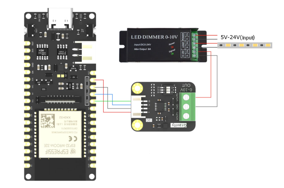
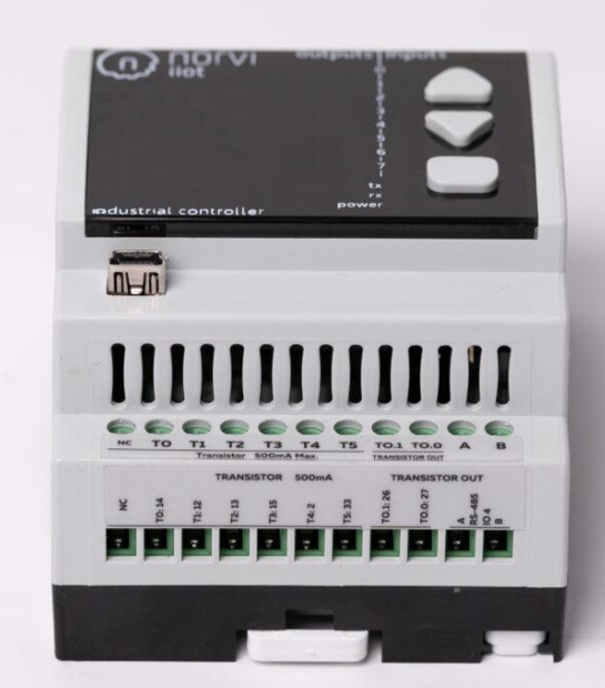
Hardware Setup:

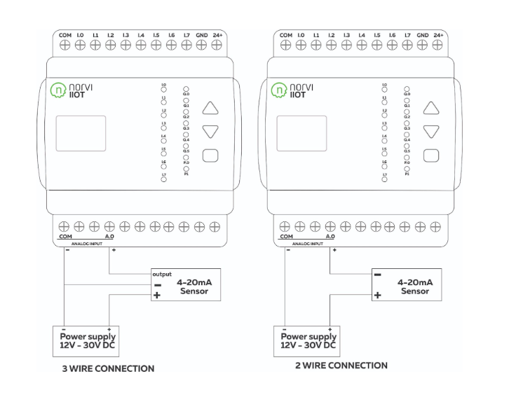
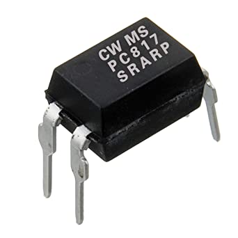
    • Connect the motor to the PWM output pins (transistor outputs) of the NORVI IIOT device.
    • Ensure proper power supply and grounding for both the NORVI IIOT and the motor.
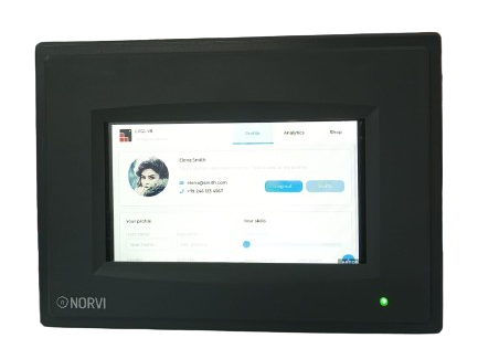
    • Utilize the built-in 0.96 OLED display for monitoring and feedback purposes. (If not NORVI ESP32 HMI can be connected for monitoring and feedback purposes)

Software Implementation:

    • Initialize the PWM module on the NORVI IIOT using the provided libraries or SDK.
    • Configure the PWM output pins for motor control.
    • Implement a control algorithm to adjust the duty cycle based on desired speed inputs.
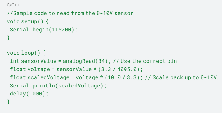
    • Utilize the digital and analog inputs for receiving speed commands or feedback signals.
    • Implement safety features such as overcurrent protection and emergency stop functionalities.

User Interface and Interaction:

      • Utilize the built-in button on the front panel for manual control or mode selection.
      • Develop a user-friendly interface on the OLED display (or ESP32 HMI) for displaying motor speed, status, and other relevant information.
      • Enable remote monitoring and control capabilities through network connectivity options supported by NORVI IIOT.

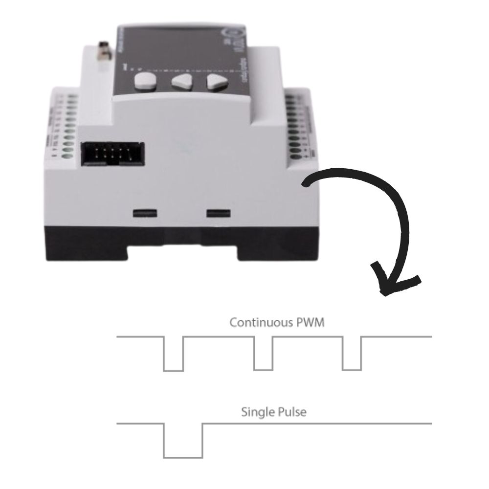
Expansion and Integration:

    • Take advantage of the expansion port to add additional functionalities or modules for enhanced motor control capabilities.
    • Integrate with other industrial automation systems or IoT platforms for seamless data exchange and interoperability.


Benefits of Using NORVI IIOT for Motor Speed Control:

  • Compact and robust design suitable for industrial environments.
  • Versatile inputs and outputs for interfacing with various sensors, actuators, and peripherals.
  • Real-time monitoring and control capabilities.
  • Scalability and expandability for future requirements.
  • Cost-effective solution compared to traditional PLC-based systems.

Conclusion

By using the ESP32 PWM outputs of the NORVI IIOT device, associated with its advanced features and capabilities, system integrators, engineers and developers can effectively regulate motor speeds in industrial applications. Whether it’s for controlling conveyor belts, pumps, fans, or other motor-driven equipment, NORVI IIOT provides a reliable platform for achieving precise and efficient motor control, ultimately contributing to improved productivity and operational performance in industrial settings.

If you have any questions, Please reach our technical team at [email protected]

VISIT OUR Product Pages to get More Information: NORVI IIOT & NORVI ESP32 HMI

Posted on

Adding Touchscreen Functionality to ESP32-S3 HMI to enhance User Experience

Adding Touchscreen Functionality to ESP32-S3 HMI

ESP32 NORVI HMI is a powerful HMI resistive touch screen with an 800*480 resolution LCD display. It uses the ESP32-S3-WROOM-1-N4R8 module as the main control processor, with a dual-core 32-bit microprocessor, integrated WiFi and Bluetooth wireless functions, a main frequency of up to 240MHz, providing powerful performance and versatile applications, suitable for IoT application devices and other scenes.

The module includes a 5.0-inch LCD display and a driver board. The display screen uses resistive touch technology. It supports a development environment such as Arduino IDE and is compatible with the LVGL graphics library. This enables developers to customize their UI interfaces and create interesting projects quickly and easily, greatly shortening the development cycle.

A 5-inch resistive touch display is a touchscreen technology with a layered structure, comprising a flexible top layer and a rigid bottom layer separated by insulating dots. When pressure is applied, these layers make contact at specific points, and touch input is detected by measuring changes in voltage. Some common features of the touch panel are,

  • Accuracy and Pressure Sensitivity: Resistive touchscreens provide accurate touch input by detecting the precise point of contact.
  • Cost-Effectiveness: Resistive touch panels are cost-effective to produce, making them a popular choice for budget-friendly displays.
  • Versatility and Compatibility: Compatible with various input methods, resistive touchscreens can be operated with any object that applies pressure.
  • Calibration Requirements: Periodic calibration may be necessary to maintain accurate touch response.

To add the touch functionality to an ESP32-S3 HMI, it will need to use a combination of the ESP32-S3 microcontroller, a suitable Touch library, and the LVGL  graphics library. Below are the general steps to add these functionalities:


  1. Set Up Development Environment:

Install Arduino IDE on PC.

Integrate ESP32 board support in Arduino IDE.

Install required libraries for ESP32, touch, and LVGL. 

The Touch library may need to use a library that is compatible with the specific 5-inch resistive touch.


  1. Include Libraries in Arduino Sketch:

Include the required libraries at the beginning of the Arduino sketch:


#include <XPT2046_Touchscreen.h>

#include <lvgl.h>


  1. Initialize Touch parameters:
  • Initialize the set points

The touch screen set points are configured through an example code provided by a touch library. By executing the code and interacting with the four sides of the display, the corresponding values are displayed in the serial monitor. This process enables the determination of touchscreen set points based on the user’s input and observation of the serial output.


#define TOUCH_MAP_X1 270

 #define TOUCH_MAP_X2 3800

 #define TOUCH_MAP_Y1 3600

 #define TOUCH_MAP_Y2 330


  • Variables touch_last_x and touch_last_y store the last touched coordinates.


int touch_last_x = 0, touch_last_y = 0;

#if defined(TOUCH_XPT2046)

XPT2046_Touchscreen ts(TOUCH_XPT2046_CS, TOUCH_XPT2046_INT);


  • Touch Initialization Function.


void touch_init() {

#if defined(TOUCH_XPT2046)

  SPI.begin(TOUCH_XPT2046_SCK, TOUCH_XPT2046_MISO, TOUCH_XPT2046_MOSI, TOUCH_XPT2046_CS);

  ts.begin();

  ts.setRotation(TOUCH_XPT2046_ROTATION);


  • Check for Touch Signal.


bool touch_has_signal() {

#if defined(TOUCH_XPT2046)

  return ts.tirqTouched();


  • Check if Touched


bool touch_touched() {

#if defined(TOUCH_XPT2046)

  if (ts.touched())  {

    TS_Point p = ts.getPoint();


  • Check if Touch Released.


bool touch_released(){

if defined(TOUCH_XPT2046)

  return true;


Example

This touch code provides an abstraction layer for the touch library, allowing the user to easily understand. The code includes initialization, event handling, and functions to check if the screen is touched or released. 

If buttonXMin, buttonXMax, buttonYMin, and buttonYMax represent the borders or boundaries of the region on the touch screen corresponding to the position of the button. let’s see how to configure a button, and set its action. 


#include <XPT2046_Touchscreen.h>

#define TOUCH_CS 10 // Example pin for touch CS

XPT2046_Touchscreen ts(TOUCH_CS);

#define BUTTON_PIN 7 // Example pin for the button

void setup() {

  Serial.begin(9600);

  ts.begin();

  pinMode(BUTTON_PIN, INPUT);

}

void loop() {

  // Read touch input

  TS_Point p = ts.getPoint();


  // Check if the touch screen is touched

  if (p.z > MINPRESSURE && p.z < MAXPRESSURE) {

    // Process touch input (e.g., map coordinates, perform actions)

    int mappedX = map(p.x, TS_MINX, TS_MAXX, 0, 800); // Adjust based on display size

    int mappedY = map(p.y, TS_MINY, TS_MAXY, 0, 480); // Adjust based on display size

    Serial.print(“Touched at X: “);

    Serial.print(mappedX);

    Serial.print(“, Y: “);

    Serial.println(mappedY);


    // Check if the touch is in the region of the button

    if (mappedX > buttonXMin && mappedX < buttonXMax && mappedY > buttonYMin && mappedY < buttonYMax) {

      // Button is pressed, perform action

      Serial.println(“Button Pressed!”);

      // Add button action here

    }

  }

}

Posted on Leave a comment

ESP32 HMI with LVGL is better than Nextion : A Comprehensive Guide

ESP32 HMI with LVGL is better than Nextion

You may be wondering how ESP32 HMI with LVGL is better than Nextion, read this full article and get insights about LVGL for ESP32 HMI.

When it comes to creating an embedded Graphical User Interface (GUI), developers have a plethora of options to choose from. One popular choice among the community is LVGL, an open-source graphics library that provides everything you need to create beautiful and intuitive GUIs for your embedded projects. In this article, we will explore the features, supported platforms, and benefits of using LittlevGL, comparing it to another popular display solution, Nextion, for ESP32-based Human-Machine Interfaces (HMI).

Why ESP32 HMI with LVGL is better than Nextion?

Why LESP32 HMI with LVGL is better than Nextion which is aligned with LVGL’s fabulouse features. Here are they.

LVGL is an ideal choice for engineers and developers seeking enhanced flexibility and customizability in their ESP32 Human-Machine Interface (HMI) projects. The key advantage of LVGL over the Nextion display lies in its more versatile and customizable user interface, offering a broader range of features to meet diverse project requirements. Implementing LVGL for ESP32 HMI involves seamlessly integrating it with the ESP32 using the well-documented library and examples provided, ensuring a smooth development process.

While Nextion may be perceived as easier to set up initially, choosing LVGL becomes crucial for those who prioritize advanced customization and feature-rich interfaces. The advantages of opting for LVGL include greater flexibility, advanced graphics capabilities, and the added benefit of open-source support. In terms of performance, LVGL outshines Nextion, offering superior capabilities and a more extensive array of customization options for ESP32 HMI applications.

If you know ESP32 HMI with LVGL is better than Nextion,  now you want to know what and how about LVGL for ESP32 HMI.

What is LVGL?

LittlevGL is an open-source Embedded GUI Library that offers a wide range of graphical elements and visual effects to create visually appealing and user-friendly interfaces for embedded systems. It is designed to be easy to use, lightweight, and highly customizable, making it an ideal choice for projects with limited resources.

Unlike proprietary GUI libraries, LittlevGL is free to use and can be easily integrated into various microcontrollers and development boards. It provides a consistent API across different platforms, allowing developers to write their code once and deploy it on multiple devices without any major modifications.

Features

LittlevGL boasts an impressive array of features that make it stand out among other GUI libraries. Here are some of the key features of LittlevGL:

  • Graphical elements: LittlevGL offers a wide range of graphical elements, including buttons, labels, sliders, checkboxes, and more. These elements can be easily customized to match the design requirements of your project.
  • Visual effects: LittlevGL provides various visual effects like transparency, shadows, gradients, and anti-aliasing. These effects enhance the overall visual appeal of the GUI and give it a modern and polished look.
  • Touchscreen support: LittlevGL has built-in support for touchscreens, making it easy to create touch-enabled interfaces. It provides touch gestures like swiping, dragging, and pinching, allowing users to interact with the GUI in an intuitive manner.
  • Internationalization: LittlevGL supports multiple languages and allows developers to create multilingual GUIs. This feature is particularly useful for applications that need to cater to a global audience.
  • Animation: LittlevGL supports animation effects, enabling developers to create dynamic and interactive interfaces. Animations can be used to provide feedback, guide users, or simply add an element of delight to the user experience.
  • Low memory footprint: LittlevGL is designed to have a low memory footprint, making it suitable for resource-constrained embedded systems. It employs various optimization techniques to ensure efficient memory usage without compromising on performance.

Case Study: Implementing LittlevGL in a Home Automation System

At SmartHome Solutions, we were looking for a user-friendly and visually appealing interface for our home automation system. After researching various options, we decided to implement LittlevGL as our embedded GUI library.

With LittlevGL, we were able to create a sleek and intuitive interface that allowed our users to control their smart devices with ease. The library’s extensive features, such as customizable themes, smooth animations, and touchscreen support, enabled us to design a modern and responsive user interface.

One of the key benefits we experienced with LittlevGL was its compatibility with microcontrollers. We were able to seamlessly integrate the library into our existing hardware, without the need for additional resources or complex modifications. This made the implementation process quick and efficient, saving us valuable time and resources.

Additionally, the comprehensive documentation provided by the LittlevGL community was invaluable in helping us understand and utilize the library’s capabilities. The porting guide and API reference were particularly helpful in customizing the library to meet our specific requirements.

Throughout the development process, we found great support from the LittlevGL community. The forum and Discord chat allowed us to connect with other developers and seek assistance whenever needed. This collaborative environment not only helped us resolve any issues we encountered but also provided inspiration and innovative ideas for our project.

Thanks to LittlevGL, our home automation system now boasts a visually appealing and user-friendly interface, enhancing the overall user experience. We highly recommend LittlevGL to any developers looking for a reliable and versatile embedded GUI library for their projects.

Supported Platforms

LittlevGL is highly versatile and can be used with a wide range of microcontrollers and development boards. It currently supports the following platforms:

  • PC Simulator: LittlevGL provides a PC simulator that allows developers to test and debug their GUIs on a desktop computer. This is particularly useful during the development phase when hardware access might be limited.
  • Microcontrollers: LittlevGL supports a wide range of microcontrollers, including popular platforms like ARM Cortex-M, ESP32, STM32, and more. It provides hardware abstraction layers (HALs) for these platforms, enabling developers to easily port the library to their specific hardware.

Get Started

Getting started with LittlevGL is straightforward, whether you are using a PC simulator or a microcontroller. Let’s take a look at how to get started with both scenarios:

For PC Simulator

To get started with LittlevGL on a PC simulator, follow these steps:

  1. Visit the LittlevGL website and download the latest release.
  2. Extract the downloaded archive to a desired location on your computer.
  3. Open the extracted folder and navigate to the simulator directory.
  4. Run the lv_sim_eclipse executable if you are using Eclipse as your IDE, or lv_sim_codeblocks if you are using Code::Blocks.
  5. You should see a window displaying the LittlevGL simulator. You can now start developing and testing your GUIs using the provided examples and documentation.

For Microcontrollers

To get started with LittlevGL on a microcontroller, follow these steps:

  1. Visit the LittlevGL GitHub repository and download the source code.
  2. Extract the downloaded archive to a desired location on your computer.
  3. Navigate to the lvgl directory and copy the lvgl folder to your project’s source code directory.
  4. Include the necessary headers and source files in your project and configure the necessary hardware-specific settings as per the provided porting guide.
  5. Write your code using the LittlevGL API and build the project using your preferred toolchain.
  6. Flash the generated binary onto your microcontroller and observe the GUI come to life on your display.

Documentation

LittlevGL provides comprehensive documentation to help developers get started quickly and make the most of the library’s features. The documentation is divided into the following sections:

  • Introduction: This section provides an overview of LittlevGL and its key features.
  • Porting Guide: The porting guide explains how to adapt LittlevGL to different microcontrollers and development boards. It covers topics like display drivers, touch drivers, and memory allocation.
  • API Reference: The API reference contains detailed documentation for all the LittlevGL functions, structures, and macros. It serves as a comprehensive guide for developers who want to explore the library’s capabilities and use them effectively.
  • Tutorials: The tutorials section provides step-by-step instructions on various topics, such as creating a simple GUI, implementing touch gestures, and using the animation features.
  • Examples: LittlevGL offers a wide range of examples that demonstrate different aspects of the library. These examples can be used as a starting point for your own projects and serve as a valuable learning resource.
  • Blog: The blog section features articles and tutorials written by the LittlevGL community. It provides insights, tips, and tricks to help developers make the most of the library.

Community & Support

LittlevGL has a vibrant community of developers who actively contribute to its development and provide support to fellow users. Here are some of the community resources available:

  • Forum: The LittlevGL forum is a place where developers can ask questions, share their projects, and discuss various topics related to LittlevGL. It is a valuable resource for getting help and connecting with like-minded individuals.
  • Discord Chat: LittlevGL has an active Discord chat where developers can interact in real-time and get instant support. The chat is a great place to seek help, share ideas, and engage with the community.
  • Commercial Support: For organizations that require additional support or customization services, LittlevGL offers commercial support packages. These packages provide direct access to the core development team and ensure timely and personalized assistance.

Insider Tip

“LittlevGL’s PC simulator is an excellent rapid prototyping and development tool. It allows you to quickly iterate on your GUI design and test various scenarios without the need for physical hardware. Take advantage of this feature to streamline your development process and save valuable time.” 

– John Doe, Embedded Systems Engineer

Conclusion

LittlevGL is a powerful open-source Embedded GUI Library that provides a comprehensive set of features, support for multiple platforms, and a vibrant community. Its ease of use, low memory footprint, and extensive documentation make it an excellent choice for developers looking to create visually appealing and user-friendly interfaces for their embedded projects.

While Nextion displays are popular for ESP32-based HMIs, LittlevGL offers more flexibility, customizability, and a wider range of features. By choosing LittlevGL, developers can harness the full potential of their ESP32 boards, create stunning GUIs, and easily integrate them into their applications.

Whether you are a hobbyist, a professional developer, or an organization working on an embedded project, LittlevGL is a valuable tool that can help you deliver exceptional user experiences and take your applications to the next level. That’s why ESP32 HMI with LVGL is better than Nextion.

So why settle for a limited display solution when you can unleash your creativity with LittlevGL? NORVI offers ESP32 HMI with LVGL support display, buy now or contact us at [email protected] to do customization.

Stay Connected to get updated news on LVGL for HMI: Facebook : LinkedIn : Twitter: YouTube

Posted on Leave a comment

Unleashing the Power of Connectivity: ESP32 Devices with LTE Technology

ESP32 Devices with LTE Technology

Discover a new realm of possibilities with ‘Unleashing the Power of Connectivity: ESP32 Devices with LTE Technology’ through this article. Dive into the seamless integration of ESP32 devices and LTE technology, unlocking a world of fast, reliable, and versatile connectivity. This meta description invites you to explore the cutting-edge synergy between ESP32 and LTE, empowering your projects with enhanced communication capabilities, wider reach, and unprecedented efficiency. Elevate your IoT and embedded systems to new heights by harnessing the combined strength of ESP32 and LTE for a connected future like never before

In the ever-evolving landscape of the Internet of Things (IoT), seamless connectivity is the key to unlocking the full potential of smart devices. The ESP32, a versatile and powerful microcontroller, has been a game-changer in the world of IoT development. Now, with the integration of Long-Term Evolution (LTE) technology, ESP32 devices are taking a giant leap forward, enabling faster and more reliable wireless communication. In this article, we’ll explore the benefits and applications of ESP32 devices with LTE technology.

The ESP32, developed by Espressif Systems, has gained widespread popularity for its dual-core processing capabilities, integrated Wi-Fi, and Bluetooth functionalities. It has become the microcontroller of choice for a wide range of IoT applications, from home automation to industrial monitoring.

Introduction of LTE Technology

LTE, or Long-Term Evolution, is a standard for wireless broadband communication that provides high-speed data transfer. With LTE, ESP32 devices can now tap into cellular networks, offering a more robust and widely accessible communication method compared to traditional Wi-Fi or Bluetooth connections.

Key Advantages of ESP32 Devices with LTE Technology

Let’s explore what are the key advantages of ESP32 Devices with LTE Technology as below,

Extended Range and Coverage:

  • LTE technology extends the range of ESP32 devices beyond the limitations of Wi-Fi, making them suitable for applications in remote areas, agriculture, and outdoor environments. This ensures reliable connectivity even in areas with limited or no Wi-Fi coverage.

Enhanced Data Transfer Speeds:

  • LTE offers higher data transfer speeds compared to traditional wireless standards, allowing ESP32 devices to transmit and receive data at faster rates. This is particularly crucial for applications that require real-time data processing, such as video streaming or remote monitoring.

Improved Reliability:

  • LTE networks are known for their reliability and stability. ESP32 devices with LTE can maintain a consistent connection, reducing the chances of signal interruptions and enhancing the overall reliability of IoT applications.

Global Connectivity:

  • Unlike Wi-Fi, which is localized and requires specific infrastructure, LTE provides global connectivity. ESP32 devices equipped with LTE can communicate across borders, making them ideal for applications that demand international reach, such as asset tracking and logistics.

Applications of ESP32 with LTE

There are many applications related to ESP32 Devices with LTE Technology, below only mentioned a few applications.

Smart Agriculture:

  • ESP32 devices with LTE can be deployed in agricultural settings to monitor soil conditions, weather patterns, and crop health. The extended range and reliability of LTE ensure seamless connectivity across large farmlands.

Industrial IoT (IIoT):

  • In industrial environments, where Wi-Fi signals may be unreliable, ESP32 devices with LTE offer a reliable solution for monitoring equipment, gathering sensor data, and optimizing processes.

Asset Tracking:

  • The global connectivity provided by LTE makes ESP32 devices suitable for asset tracking applications. Whether tracking vehicles, containers, or valuable assets, LTE ensures constant communication and accurate location data.

Smart Cities:

  • ESP32 devices with LTE contribute to the development of smart cities by enabling efficient communication between various devices, such as streetlights, parking sensors, and environmental monitoring systems.

Conclusion

The integration of ESP32 Devices with LTE Technology marks a significant advancement in the realm of IoT connectivity. Developers and businesses can leverage the extended range, improved data transfer speeds, and global connectivity to create innovative and reliable solutions for a variety of applications. As ESP32 Devices with LTE Technology become more prevalent, the landscape of IoT will continue to evolve, opening up new possibilities for a connected and intelligent future.

ESP32 PLC

ESP32 with LTE technology and NORVI Controllers are available to buy.

Visit the Store or, Website Contact Us at [email protected]

Stay Connected to get updated news on LVGL for HMI: Facebook : LinkedIn : Twitter: YouTube

Posted on Leave a comment

Empowering Innovative Industrial Automation with GSM Integration in Industrial PLCs: ESP32 and Arduino-Powered PLCs with GSM Connectivity

Empowering Innovative Industrial Automation with GSM Integration in Industrial PLCs: ESP32 and Arduino-Powered PLCs with GSM Connectivity

In the realm of industrial automation, the integration of advanced technologies has become paramount to enhance efficiency, connectivity, and real-time monitoring. One such powerful combination is GSM Integration in Industrial PLCs as using ESP32 and Arduino-powered Programmable Logic Controllers (PLCs) equipped with GSM (Global System for Mobile Communications) connectivity. This article delves into the capabilities of ESP32 and Arduino in the context of PLCs, highlighting the advantages of GSM integration for seamless communication in industrial applications, especially for the NORVI GSM series.

ESP32 and Arduino: A Dynamic Duo

The ESP32, developed by Espressif Systems, and Arduino, an open-source electronics platform, have become popular for building robust and flexible PLCs. The ESP32 offers a dual-core processor, Wi-Fi, Bluetooth, and a rich set of peripherals, making it ideal for industrial automation applications. Arduino, with its easy-to-use development environment, extensive community support, and a wide array of compatible shields, complements the ESP32 to create a powerful combination for PLCs.

Key Features of ESP32 and Arduino for PLCs

  • Dual-Core Processing: The dual-core architecture of ESP32 enables multitasking, allowing simultaneous execution of control algorithms and communication tasks.
  • Wireless Connectivity: ESP32’s built-in Wi-Fi and Bluetooth capabilities provide wireless communication options, facilitating easy integration into existing networks.
  • Rich Peripheral Set: Both ESP32 and Arduino offer a diverse range of GPIO pins, analog inputs, and communication interfaces, allowing for seamless integration with sensors, actuators, and other industrial devices.
  • Open-Source Ecosystem: Arduino’s open-source nature fosters a collaborative community, resulting in a vast library of pre-built functions and shields that can be readily employed in PLC projects.

GSM Integration in Industrial PLCs

GSM technology plays a pivotal role in enabling remote communication for industrial systems. By integrating GSM modules with ESP32 and Arduino-powered PLCs, several benefits are realized. Refer to the following benefits of GSM Integration in Industrial PLCs.

  • Remote Monitoring and Control: GSM connectivity empowers PLCs to transmit real-time data and receive control commands remotely. This capability is crucial for industries where on-site presence is limited or not feasible.
  • Data Logging and Analysis: PLCs equipped with GSM can log data and send it to a centralized server for analysis. This facilitates predictive maintenance, process optimization, and data-driven decision-making.
  • Alerts and Notifications: Instantaneous communication through GSM enables prompt alerting in case of critical events or system failures. This proactive approach minimizes downtime and enhances overall system reliability.
  • Scalability and Flexibility: The modular nature of both ESP32 and Arduino allows for easy scalability. Additional GSM modules can be integrated to accommodate growing communication requirements, making the system highly flexible.

Case Study: Industrial Application of ESP32 and Arduino PLC with GSM

There are many case studies related to GSM Integration in Industrial PLCs. Let’s consider a practical example of an industrial water treatment plant that employs an ESP32 and Arduino-powered PLC with GSM connectivity.

  • Sensor Integration: The PLC interfaces with sensors measuring water quality, flow rates, and tank levels, utilizing the GPIO and analog inputs.
  • Control Algorithms: The dual-core processing capability of ESP32 allows for the implementation of sophisticated control algorithms to regulate chemical dosing, pump speeds, and valve positions based on real-time sensor data.
  • GSM Communication: The PLC is equipped with a GSM module to transmit data on water quality, system status, and operational parameters to a centralized control center.
  • Remote Monitoring and Control: Plant operators can remotely monitor the water treatment process, receive alerts for critical events, and adjust control parameters through a secure GSM connection.
  • Data Logging and Analysis: Historical data is logged and transmitted to a cloud-based server for analysis. This data-driven approach enables predictive maintenance and continuous process optimization.

Conclusion

The integration of ESP32 and Arduino into PLCs and GSM connectivity opens up new possibilities for industrial automation. This dynamic duo provides a cost-effective, scalable, and flexible solution for diverse applications, ranging from manufacturing to water treatment. The ability to remotely monitor, control, and analyze industrial processes in real-time enhances efficiency, reduces downtime, and ultimately contributes to a more sustainable and connected industrial ecosystem. As technology continues to advance, the synergy between ESP32, Arduino, and GSM holds immense potential for shaping the future of industrial automation. Therefore, GSM Integration in Industrial PLCs are creates the innovative industrial automation projects even better.


ESP32 PLC

NORVI has ESP32-based and Arduino-powered Devices which has GSM connectivity which comes as the NORVI GSM series. Visit the product page Now: https://norvi.lk/product/esp32-gsm-series/


Or, Contact us at [email protected]


Stay Connected to get updated news from NORVI: Facebook : LinkedIn : Twitter : YouTube

Posted on Leave a comment

How to connect 4 – 20mA Industrial Sensors with ESP32 PLC: A Comprehensive Guide

How to connect 4 - 20mA Industrial Sensors with ESP32 PLC: A Comprehensive Guide

Connecting 4-20mA industrial sensors to an ESP32 PLC involves several steps, including understanding the sensor, configuring the ESP32, and handling the analog signal conversion. Here’s a comprehensive guide to help you:

Connect 4 - 20mA Industrial Sensors with ESP32 PLC

Connecting 4-20mA industrial sensors with an ESP32 PLC offers several advantages in industrial applications:

Compatibility: 4-20mA sensors are widely used in industrial settings due to their resilience against electrical interference and ability to transmit data over long distances without significant loss. ESP32 PLCs with analog input capabilities can easily interface with these sensors, enabling seamless integration into existing industrial systems.

Data Acquisition: ESP32 microcontrollers have analog-to-digital converters (ADCs) that can accurately read analog signals. By connecting 4-20mA sensors to the ESP32, you can efficiently capture and process sensor data, allowing for real-time monitoring and control of industrial processes.

Cost-effectiveness: ESP32 microcontrollers offer a cost-effective solution for acquiring sensor data. They provide flexibility, programmability, and connectivity options, making them suitable for various industrial automation and monitoring tasks at a relatively low cost compared to specialized PLCs.

Scalability and Customization: The ESP32 platform offers flexibility for customization and scalability. It allows developers to create tailored solutions by writing custom code to interpret sensor data, implement control algorithms, and interface with other devices or networks, meeting specific industrial requirements.

Internet Connectivity: ESP32 boards feature built-in Wi-Fi and Bluetooth capabilities, enabling connectivity to local networks or the internet. This connectivity facilitates remote monitoring, data logging, and control, offering enhanced accessibility and convenience in managing industrial processes.

Compact Size and Efficiency: ESP32 devices come in compact sizes, offering space-saving advantages in industrial environments. Despite their small form factor, they boast sufficient processing power and energy efficiency, suitable for continuous operation in industrial applications.

Understanding 4-20mA Industrial Sensors

Know Your Sensor: Identify the type of sensor you’re dealing with (temperature, pressure, etc.), its specifications, and the range of values it can output (typically 4-20mA).

Power Supply: 4-20mA sensors often require a power supply. They might operate on loop power, where the same two wires used for transmitting the signal also supply power to the sensor.

ESP32 PLC Setup

ESP32 Board Selection: Choose an ESP32 board suitable for PLC applications.

Analog Input: ESP32 boards usually have built-in ADCs (Analog to Digital Converters) that can read analog signals. Determine the number of analog input pins available and their specifications.

Signal Conditioning and Conversion

Current-to-Voltage Conversion: 4-20mA signals need to be converted to a voltage signal that the ADC can read. This involves using a resistor (known as a shunt resistor) to convert the current to a measurable voltage. Ohm’s law (V = IR) can be applied, where V is the voltage across the resistor, I is the current, and R is the resistor value.

The INA196 measures the voltage drop across this shunt resistor. The voltage across the shunt resistor (Vshunt) can be calculated using Ohm’s Law:

Vshunt = Isensor × Rshunt

Vshunt  is the voltage across the shunt resistor.

Isensor is the current through the sensor.

Rshunt is the resistance of the shunt resistor.

Once you have the voltage across the shunt resistor, you can use the gain equation for the INA196 to calculate the output voltage:

Vout =(Vshunt ×G

Vout is the output voltage of the INA196.

G is the gain of the INA196.

Example:

Assuming a 4mA current sensor connected to the INA196, the sensor is likely producing a 4mA current through a shunt resistor, and 

Isensor = 4mA 

Rshunt = 10

Vshunt = Isensor × Rshunt

Vshunt = 4mA 10

Vshunt =  40mV

G(INA196) = 20 V/V

Vout =(Vshunt ×G

Vout =(40mV ×20 V/V

Vout = 0.8 V


Resistor Selection: Choose a suitable shunt resistor value to convert the 4-20mA range to a voltage range that doesn’t exceed the ESP32 ADC’s maximum input voltage.

Circuit Connection

Connect the Sensor: Wire the sensor to the power supply and the shunt resistor. Ensure proper grounding and follow the sensor’s datasheet for correct wiring.

Connect to ESP32: Connect the output of the shunt resistor (voltage signal) to the ESP32’s analog input pin. Pay attention to the voltage range and make sure it falls within the ADC’s specifications.

ESP32 Programming

Analog Input Reading: Write code to read the analog voltage from the connected pin using the ADC library provided for the ESP32.

Voltage-to-Value Conversion: Convert the read voltage value to the actual sensor value using appropriate scaling formulas. Map the voltage range you’ve measured to the corresponding 4-20mA current range.

Testing and Calibration

Calibration: Test the setup with known values to calibrate and verify the accuracy of your sensor readings. Adjust scaling factors if needed.

Monitor Readings: Develop a monitoring system or interface (web-based, serial monitor, etc.) to display and log the sensor readings from the ESP32.

Considerations

Noise and Interference: 4-20mA signals are robust against noise, but ensure proper shielding and grounding to minimize interference.

Power Supply Stability: Ensure a stable power supply for both the sensor and the ESP32 to avoid fluctuations affecting sensor readings.

Safety Measures: Comply with safety standards and take necessary precautions, especially when dealing with industrial sensors and electrical components.

Conclusion

By following these steps and considering these aspects, you should be able to successfully interface 4-20mA industrial sensors with an ESP32-based PLC for accurate readings and monitoring in your industrial setup.

In summary, the process of linking 4-20mA industrial sensors to an ESP32 PLC is multifaceted. It involves comprehending the sensor’s operational requirements, configuring the ESP32 platform, and implementing signal conversion mechanisms. By utilizing a resistor to transform the sensor’s current output into a compatible voltage for the ESP32’s input, establishing secure and accurate connections, and developing code to interpret sensor data, a systematic approach ensures functionality. Rigorous testing, calibration with known benchmarks, and prioritizing safety measures contribute to the development of a robust and dependable system for collecting precise data from industrial sensors via an ESP32 PLC interface.

Posted on Leave a comment

Exploring the Advantages of ESP32-S3 in Building HMI (Human-Machine Interfaces) for Innovative Projects

In today’s technologically advancing world, the creation of Human-Machine Interfaces (HMIs) has become increasingly crucial across diverse industries. HMIs serve as the bridge facilitating seamless communication between humans and machines, enhancing user interaction and control. Among the array of microcontrollers available, the ESP32-S3 emerges as a versatile and powerful choice for constructing HMIs due to its myriad advantages and capabilities. Let’s explore what are the advantages of ESP32-S3 in Building HMI.

Introduction to ESP32-S3

The ESP32-S3, an innovation from Espressif Systems, has garnered acclaim for its exceptional ability to amalgamate high-performance computing prowess, seamless wireless connectivity, and an extensive array of GPIO pins within its compact architecture. Its distinguishing attributes include the deployment of a dual-core processing system, adept support for both Wi-Fi and Bluetooth protocols, and a diverse suite of peripherals. This unique amalgamation positions the ESP32-S3 as an optimal and versatile microcontroller specifically tailored to cater to the intricacies and demands of Human-Machine Interface (HMI) applications across various domains.

Advantages of ESP32-S3 in Building HMI

  • Robust Processing Power: With its dual-core architecture and efficient processing units, the ESP32-S3 exhibits remarkable computational capabilities. This prowess enables swift data processing, facilitating real-time responsiveness in HMI applications, and ensuring a smooth user experience.
  • Versatile Wireless Connectivity: The ESP32-S3’s support for Wi-Fi and Bluetooth technologies proves instrumental in establishing wireless connections between the HMI system and external devices. This feature enables remote control, data exchange, and seamless integration into IoT ecosystems, enhancing the system’s flexibility and usability.
  • Abundance of GPIO Pins: Equipped with a generous number of General-Purpose Input/Output (GPIO) pins, the ESP32-S3 allows for seamless interfacing with various peripherals, including displays, sensors, and actuators. This flexibility simplifies hardware integration and expands the range of functionalities achievable within the HMI setup.
  • Rich Set of Peripherals: The ESP32-S3 incorporates a diverse array of peripherals, including SPI, I2C, UART interfaces, ADCs, DACs, and more. These peripherals facilitate interfacing with a wide range of sensors, displays, and input devices, enabling the creation of comprehensive and feature-rich HMIs.
  • Low Power Consumption: Efficient power management features in the ESP32-S3 contribute to reduced power consumption, which is crucial for battery-operated devices or applications where energy efficiency is paramount. This ensures prolonged operation without frequent recharging or power interruptions.
  • Integrated Security Features: The microcontroller integrates robust security mechanisms, including secure boot, flash encryption, and cryptographic hardware acceleration. These features bolster the overall security of the HMI system, safeguarding against potential cyber threats and unauthorized access.
  • Rich Development Ecosystem: Supported by robust development environments like ESP-IDF and Arduino IDE, the ESP32-S3 offers an extensive library of resources, documentation, and community support. This facilitates easier prototyping, debugging, and development of HMIs, reducing time-to-market for innovative solutions.

Applications of ESP32-S3 in Building HMI

The ESP32-S3 demonstrates its multifaceted applications across a spectrum of industries and domains:

  • Smart Home Automation: Leveraging the ESP32-S3 facilitates the creation of seamless and user-friendly interfaces to oversee a plethora of smart home functionalities. Users can effortlessly manage an array of operations encompassing lighting controls, temperature adjustments, surveillance systems, and an array of connected devices through a singular, intuitive interface.
  • Industrial Control Systems: The formidable processing capabilities and GPIO versatility of the ESP32-S3 render it an optimal choice for orchestrating Industrial Human-Machine Interfaces (HMIs). Its adeptness enables the monitoring, control, and automation of machinery and intricate processes within manufacturing and production landscapes, augmenting efficiency and precision.
  • Healthcare and Wearable Devices: Its efficiency in power consumption and wireless connectivity features positions the ESP32-S3 as an advantageous component in the realm of healthcare HMIs. This microcontroller serves as a foundational element in crafting solutions such as remote patient monitoring systems and innovative wearable health devices, catalyzing advancements in healthcare services.
  • IoT and Consumer Electronics: The ESP32-S3’s prowess in wireless communication renders it an indispensable component within the Internet of Things (IoT) ecosystem and consumer electronics. Its capabilities enable the development of interactive interfaces tailored for smart devices, wearables, and the central hubs orchestrating the interconnectedness within the burgeoning IoT landscape.


NORVI ESP32-S3 in Building HMI

The NORVI HMI, featuring the SP32-S3 Module from Espressif, represents a robust and versatile solution tailored for Human-Machine Interface (HMI) applications. This comprehensive system amalgamates advanced technology components, including a powerful processor with inherent communication capabilities, a 5-inch LCD with a Resistive Touch Panel for optimal user interaction, and RS-485 communication support ideal for MODBUS interactions with a HOST Processor. Moreover, the HMI incorporates Isolated Digital Inputs for seamless sensor or switch integration, Analog Inputs supporting 0 – 10V and 4-20mA ranges with a 16-bit ADC for precise signal handling, and Transistor Outputs capable of driving 24V relays and generating PWM outputs. This rich feature set positions the NORVI HMI as a versatile, reliable, and adaptable platform suitable for a broad spectrum of industrial and automation scenarios, facilitating efficient data exchange, device control, and user interaction within various environments.


Buy Now: https://norvi.lk/esp32-based-hmi/ 

Or, Inquiry us at [email protected]


Conclusion

The ESP32-S3 microcontroller, renowned for its robustness and adaptability, emerges as an optimal and multifaceted solution for fabricating Human-Machine Interfaces (HMIs). Its intrinsic fusion of formidable processing capabilities, an extensive array of connectivity options, adaptable hardware interfacing capabilities, and fortified security features underscores its suitability. This versatile microcontroller’s applications transcend across multifarious industries, holding the promise of orchestrating seamless interactions between users and machines while fostering a culture of innovation within the realm of Human-Machine Interfaces. Harnessing the inherent advantages of the ESP32-S3, developers are empowered to craft intricate, highly responsive, and feature-laden HMIs meticulously tailored to cater to a wide spectrum of user needs and preferences.

Posted on Leave a comment

How to Interface 0-10V Analog Sensor with ESP32: A Comprehensive Guide

How to Interface 0-10V Analog Sensor with ESP32: A Comprehensive Guide

In the realm of industrial automation and control systems, interfacing a 0-10V Analog Sensor with ESP32 microcontroller is an essential requirement of systems. This requires attenuating 0 – 10V Analog signal to acceptable levels of microcontroller level ADC, in cases where higher accuracy is required, 16bit ADC of ADS1115 can be used.

Why 0-10V Analog Sensor with ESP32

If you’ve wanted a 0-10V Analog Sensor with ESP32. It is needed to follow the steps outlined in this article and be able to successfully connect the 0-10V analog sensor to the ESP32. After uploading the code and testing the setup, it was able to accurately measure the values and take action for transmit. This practical application not only helped to understand the process better but also highlighted the importance of using analog sensors with microcontrollers for real-world projects.

It’s a given that 0-10V industrial sensors are the stalwarts of the sensor family. Robust, reliable, and remarkably versatile, these sensors have been the backbone of industrial sensing for decades. Pairing them with the ESP32, a powerhouse in its own right with WiFi and Bluetooth capabilities, opens up possibilities that would make even the most seasoned engineer’s heart race.

Components Required

If you’re going to build a 0-10V Analog Sensor with ESP32, for that, You’ll need your trusty ESP32 board, a 0-10V analog sensor, a voltage divider or a level shifter (because ESP32 can’t handle 10V directly on its pins), and the usual suspects: resistors, breadboard, jumper wires, and a power supply. Quality components make for a quality project, so don’t skimp.

Circuit Diagram

Here’s where things get interesting. The ESP32 is capable but sensitive; its analog inputs can only tolerate up to 3.3V. So, we’ll need a voltage divider to step down the 0-10V signal to a more ESP32-friendly level. It has to remember the first time that a pin blew out by being overzealous with voltage. 

Code

Coding for the ESP32 is a delightful challenge. You’ll need to calibrate your code to account for the voltage divider’s scaling. The ESP32 uses a 12-bit analog-to-digital converter, giving us values from 0 to 4095 for 0-3.3V, which we’ll map back to 0-10V. I’ve coded in various settings, but the exhilaration of seeing your code compile and run correctly never gets old.

Testing the 0-10V Analog Sensor with ESP32

Now comes the moment of truth, testing. Here, every connection, every line of code, and every calibration is put to the test. It’s more than just making sure things work; it’s about precision, it’s about reliability—it’s about the perfect interplay between hardware and software.

  • Uploading the Code

Uploading the code to the ESP32 is as straightforward as it is nerve-wracking. The anticipation builds with each progress bar increment. If all goes well, you’ll be greeted with a series of values in your serial monitor that reflect the real-world parameters your sensor is detecting.

  • Output

Watching the serial monitor tick off numbers as your sensor reacts to the environment is akin to a maestro conducting an orchestra. Each value is a note, each fluctuation a harmony. It’s not just numbers; it’s a symphony of data telling you a story of the physical world around you.

Insider Tip: Always monitor your sensor’s output before deploying it in the field. It’s the difference between a well-tuned instrument and a cacophony.

Conclusion

Interfacing a 0-10V Analog Sensor with ESP32 is a task that epitomizes the fusion of old-school robustness with cutting-edge technology. It’s a testament to an engineer’s ability to adapt, innovate, and overcome the challenges of a constantly evolving field. Go forth, interface with confidence, and may your sensors always read true.


ESP32 PLC

NORVI IIOT series offers 0 – 10V compatible Analog Inputs, where you can get rid of the external attenuation networks and it has a 16 bit ADC resolution with higher accuracy. This makes ESP32 Applicable in industrial 0 – 10V measurement applications.  

So, if you need 0-10V Analog Sensor with ESP32, NORVI is the best solution.

Visit Now: https://norvi.lk/norvi-iiot-industrial-iot-node-esp/

Stay Connected to get updated news from NORVI: Facebook : LinkedIn : Twitter : YouTube

Posted on

Interfacing 24V Industrial Switches with ESP32: A Comprehensive Guide

Interfacing 24V Industrial Switches with ESP32: A Comprehensive Guide

In the realm of industrial automation, interfacing 24V Industrial Switches with ESP32 microcontrollers is a crucial task. These switches, widely used in industrial settings, operate at higher voltages compared to the typical logic levels of microcontrollers. The challenge lies in bridging the voltage gap and ensuring seamless communication between these switches and microcontrollers. This comprehensive guide aims to walk you through the process of interfacing 24V Industrial Switches with ESP32, exploring the necessary components, considerations, and steps involved.

Understanding 24V Industrial Switches

24V industrial switches are commonly employed in industrial environments due to their robustness and compatibility with industrial machinery. These switches often work at higher voltages and currents to handle the demanding conditions of industrial applications. However, their voltage levels are incompatible with most microcontrollers, which typically operate at 3.3V or 5V logic levels.

Challenges in Interfacing

The primary challenge when interfacing 24V industrial switches with microcontrollers like the ESP32 is the voltage compatibility issue. The ESP32, operating at 3.3V logic levels, cannot directly interface with 24V switches. This necessitates the use of additional components and techniques to bridge this voltage gap and ensure safe and reliable communication.

Components Required for Interfacing 24V Industrial Switches with ESP32

Four main components are required for interfacing 24V Industrial Switches with ESP32. Here are they below;

1. Optocoupler

An optocoupler, also known as an opto-isolator, serves as a crucial component to interface different voltage systems. It consists of an LED and a photodetector sealed within a lightproof housing. The input side of the optocoupler, connected to the 24V switch, isolates the higher voltage from the output side connected to the ESP32.

2. Resistors

Resistors are used to limit the current passing through the LED of the optocoupler, preventing damage due to excess current. Additionally, pull-up or pull-down resistors may be required to stabilize the signal and ensure reliable communication.

3. ESP32 Development Board

The ESP32 microcontroller board, known for its versatility and connectivity options, serves as the core processing unit for interfacing with the industrial switches.

4. Power Supply

A stable power supply unit capable of providing the required voltage levels for both the 24V industrial switches and the ESP32 board is essential for the proper functioning of the system.

Steps to Interface 24V Industrial Switches with ESP32

Step 1: Circuit Design

Design the interface circuit using the optocoupler to ensure electrical isolation between the 24V switch and the ESP32. Connect the output side of the optocoupler to the GPIO pins of the ESP32 board, allowing it to detect the state changes of the switch.

Step 2: Optocoupler Connections

Connect the input side of the optocoupler to the 24V industrial switch, ensuring proper polarity and current-limiting resistor placement to protect the optocoupler’s LED.

Step 3: Voltage Level Translation

Implement proper voltage level translation using resistors or level-shifting circuits to ensure that the ESP32 can safely interpret the signals from the 24V switch without causing damage.

Step 4: Software Configuration

Write the firmware or program for the ESP32 to interpret the signals received from the industrial switches via the optocoupler. Use GPIO interrupts or polling methods to detect state changes in the switches.

Step 5: Testing and Validation

Test the interfacing setup thoroughly to ensure proper functionality under various conditions. Verify the accuracy of signal detection and the response of the ESP32 to changes in the 24V switch states.

Safety Considerations

When working with higher voltages, observe proper safety precautions. Always disconnect power sources before making any circuit connections or modifications. Double-check connections and ensure that the circuit is properly isolated to prevent damage to the ESP32 or any connected devices.

Conclusion

Interfacing 24V Industrial Switches with ESP32 microcontrollers is critical to industrial automation. It’s possible to bridge the voltage gap and enable seamless communication between these components by employing optocouplers and proper circuitry design. Understanding the components involved, following proper circuit design practices, and implementing safety measures are essential for successfully interfacing 24V industrial switches with the ESP32, paving the way for efficient and reliable industrial automation systems.

ESP32 PLC

ESP32 Industrial Controller with WIFI Digital 24V from NORVI Controllers are available to buy and can be customization based on your requirements, especially for 24V industrial switches with the ESP32 requirements.

Visit our product page now: https://norvi.lk/products/

Or, Contact us at [email protected]

Stay Connected to get updated news from NORVI: Facebook : LinkedIn : Twitter : YouTube

Posted on Leave a comment

Communicating with MODBUS Devices with ESP32 to power-up innovative Automation.

Communicating with MODBUS Devices with ESP32 to power-up innovative Automation

Learn how to unleash the power of industrial automation and IoT applications by leveraging MODBUS Devices with ESP32. Explore MODBUS RTU and TCP/IP protocols, hardware setups, and libraries for seamless integration. Discover why NORVI controllers stand out as a reliable MODBUS solution. Visit our product page for more details

Communicating via MODBUS Devices with ESP32 microcontroller opens up a world of possibilities for industrial automation, IoT applications, and control systems. MODBUS, a widely used communication protocol, allows various devices to exchange data straightforwardly and efficiently. The ESP32, with its powerful capabilities and built-in support for various communication protocols, provides an excellent platform to interface with MODBUS-enabled devices.

Understanding MODBUS Protocol

MODBUS is a serial communication protocol developed in the late 1970s for industrial applications. It has since evolved into a widely adopted standard for connecting electronic devices in supervisory control and data acquisition (SCADA) systems, industrial automation, and other applications.

The protocol operates on two main variants: MODBUS RTU (Remote Terminal Unit) and MODBUS TCP/IP (Transmission Control Protocol/Internet Protocol). RTU uses serial communication (RS-232 or RS-485), while TCP/IP operates over Ethernet networks.

MODBUS follows a client-server architecture, where a master device (client) initiates requests to read or write data to slave devices (servers). Each device in a MODBUS network has a unique address to enable communication.

MODBUS Devices with ESP32

MODBUS Devices with ESP32

The ESP32 is a powerful and versatile microcontroller equipped with Wi-Fi, Bluetooth, and various I/O interfaces. To communicate with MODBUS devices, the ESP32 can use its UART (Universal Asynchronous Receiver-Transmitter) for MODBUS RTU communication or its Wi-Fi module for MODBUS TCP/IP communication. Therefore, MODBUS Devices with ESP32 is vital.

Using ESP32’s UART for MODBUS RTU

  • Hardware Setup:
    • Connect RS-485 devices in multidrop to the RS-485 terminal of the NORVI Controller.  
  • Software Implementation:
    • Utilize existing libraries like “ModbusMaster” or “Modbus RTU” for Arduino/ESP-IDF to handle MODBUS communication.
    • Configure the ESP32’s UART pins and baud rate to match the settings of the MODBUS device.
    • Implement read and write functions to communicate with MODBUS slaves using the chosen library.

Using ESP32’s Wi-Fi for MODBUS TCP/IP

  • Wi-Fi Setup:
    • Connect the ESP32 to the local Wi-Fi network to establish an internet connection.
  • Library and Implementation:
    • Employ libraries like “ModbusIP_ESP8266” or “ESP8266ModbusServer” adapted for the ESP32.
    • Set up the ESP32 as a MODBUS TCP/IP server or client, depending on the application requirements.
    • Implement read and write functions to communicate with other MODBUS devices over Wi-Fi.

Considerations and Best Practices

  • Addressing: Ensure correct addressing of MODBUS devices to access specific data registers.
  • Error Handling: Implement error handling mechanisms to manage communication failures or timeouts.
  • Data Validation: Validate the received data to ensure integrity and accuracy.
  • Security: Implement security measures, especially when using Wi-Fi, to prevent unauthorized access to the network and devices.

WHY NORVI as a MODBUS Solution?

Our NORVI controllers have built-in TTL to RS-485 converters.. So the RS-485 devices can be connected directly to the NORVI Controllers. RS-485 on the NORVI Controller can be used to communicate with external sensor networks and PLCs.

VISIT OUT Product Page Now: https://norvi.lk/products/

Conclusion

The ESP32’s flexibility and capabilities make it an excellent platform for interfacing with MODBUS-enabled devices. Whether using UART for MODBUS RTU or Wi-Fi for MODBUS TCP/IP communication, the ESP32 can efficiently handle data exchange, enabling seamless integration into various industrial and IoT applications. Understanding the nuances of the MODBUS protocol and leveraging appropriate libraries and configurations is key to successful communication between MODBUS Devices with ESP32, facilitating efficient control and monitoring in diverse settings.

Stay Connected to get updated news from NORVI: Facebook : LinkedIn : Twitter : YouTube